
Physics
- Units & Measurements
- Vectors
- Motion
- Work, Energy & Power
- Equilibrium of Forces
- Density and Pressure
- Newton’s Laws of Motion
- Heat & Temperature I
- Thermal Expansivity
- Heat & Temperature II
- Waves
- Light Waves & Optics
- Curved Mirrors & Lenses
- Sound Waves
- Electricity
- Fields
- AC Circuits
- Atomic Physics
- Nuclear Physics
UNITS & MEASUREMENTS
PHYSICAL QUANTITIES
A quantity that has measurable physical properties like length, mass e.t.c. is a physical quantity.
To measure a physical quantity, we need to specify two things; the number and its unit of measurement
For example: A man is 3m tall and has a mass of 55kg
There are two types of physical quantities:
1. Fundamental Quantities
These are the basic quantities that provide the basic unit of measurement. They form the base unit upon which other units depend.
| Fundamental quantities | Units | Unit abbreviation |
|---|---|---|
| Length | Metre | m |
| Mass | Kilogram | kg |
| Time | Second | s |
| Temperature | Kelvin | k |
| Electric current | Ampere | A |
| Amount of substance | Mole | mol |
| Luminous intensity | Candela | cd |
2. Derived Quantities
These quantities are obtained by combining two or more fundamental quantities. When we multiply or divide two or more fundamental quantities, we have a derived quantity.
| Derived quantity | Derivation | unit |
|---|---|---|
| Area | length × breadth | m2 |
| Speed or velocity | distance/time | m/s |
| Acceleration | change in velocity/time | m/s2 |
| Force | mass × acceleration | kgm/s2 |
| Density | mass/volume | kg/m3 |
| Work or Energy | force × distance | kgm2/s2 |
Multiples and submultiples of units
One single unit may be too big or too small to measure some quantities.
For example, the length or the distance between Lagos and London is too big to be measured in metres. Again also, the mass of a cube of sugar is too small to be measured in kilograms. Hence, we can break the units into smaller parts using the prefixes
| Multiples | Prefix |
| × 103 | Kilo (k) |
| × 106 | Mega (M) |
| × 109 | Giga (G) |
| × 1012 | Tera (T) |
| Sub-multiples | Prefix |
| × 10-2 | centi (c) |
| × 10-3 | milli (m) |
| × 10-6 | micro (μ) |
| × 10-9 | nano (n) |
| × 10-12 | pico (p) |
Example: What is 3hours + 55minutes + 35seconds in S.I. units
60 minutes = 1 hour
∴ 3 hours = 3 × 60 minutes = 180 minutes
1 minute = 60 seconds
180 minutes = 180 × 60 = 10800 seconds
55minutes = 55 × 60 = 3300 seconds
35 seconds = 35 seconds
Total = 14,135 seconds
Example: What is the volume of a cuboid with dimensions 1.6m by 5cm by 2mm
HINT: Volume of cuboid = l × b × h
length = 1.6m
breadth = 5cm = 5 × 10⁻² m = 0.05 m
height = 2mm = 2 × 10⁻³ m = 0.002
volume = 1.6 × 0.05 × 0.002 = 0.000016 m3 or 1.6×10⁻⁵ m3
REMEMBER: A number can be represented in Standard form A × 10n where A is a number between 1 and 10 and n is an integer (+ve or –ve whole number)
Dimensions of Physical Quantities
The dimensions of a physical quantity show how that quantity is made up in terms of the fundamental quantities mass (M), length (L) and time (T)
e.g. speed = distance/time
Since distance is a measure of length(L), then the dimension of speed becomes L/T or LT-1

Applications of Dimensions
It can be used to determine whether a physical equation is correct or not

Dimensioning helps to derive the exact relationship between physical quantities where the formula cannot be easily obtained
Example: The period T of an oscillation of a simple pendulum depends on the length l, and acceleration g. Determine the exact form of dependence
Let us assume T = la gb where a and b are constants
Dimension of period T is T
Dimension of length l is L
Dimension of acceleration g is velocity/time = (s/t)/t = s/t2 = LT-2
∴ T = La (LT-2)b
T = La Lb T-2b simplifies to T = La+b T-2b
Equating the indices for each term on both sides
For T; 1 = -2b…(i) when T1 is compared with T-2b
For L; 0 = a + b…(ii) when L0 compared with La+b
from (i): b = -1/2
Substituting this in equation (ii)
0 = a + (-1/2) ⇒ a = 1/2
Thus, T = l 1/2 g-1/2 OR T = √(l/g)
MEASUREMENTS
It is important to measure physical quantities as accurately as possible in order for them to be useful. In this section, we will discuss the instruments for measuring the three basic quantities length, time and mass and some others
Measurement of Length
Length can be measured using the following instruments: metre rule, tape rule, Vernier calipers and micrometre screw gauge. The use of a particular instrument depends on the following factors
- The distance, size and shape of what is to be measured
- The degree of accuracy
The unit of measurement of length is metre (m)
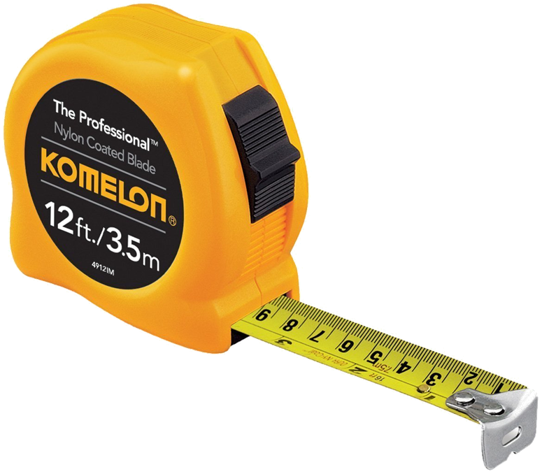
Tape Rule
Large distances such as the length of a field or playground can be measured using a tape rule
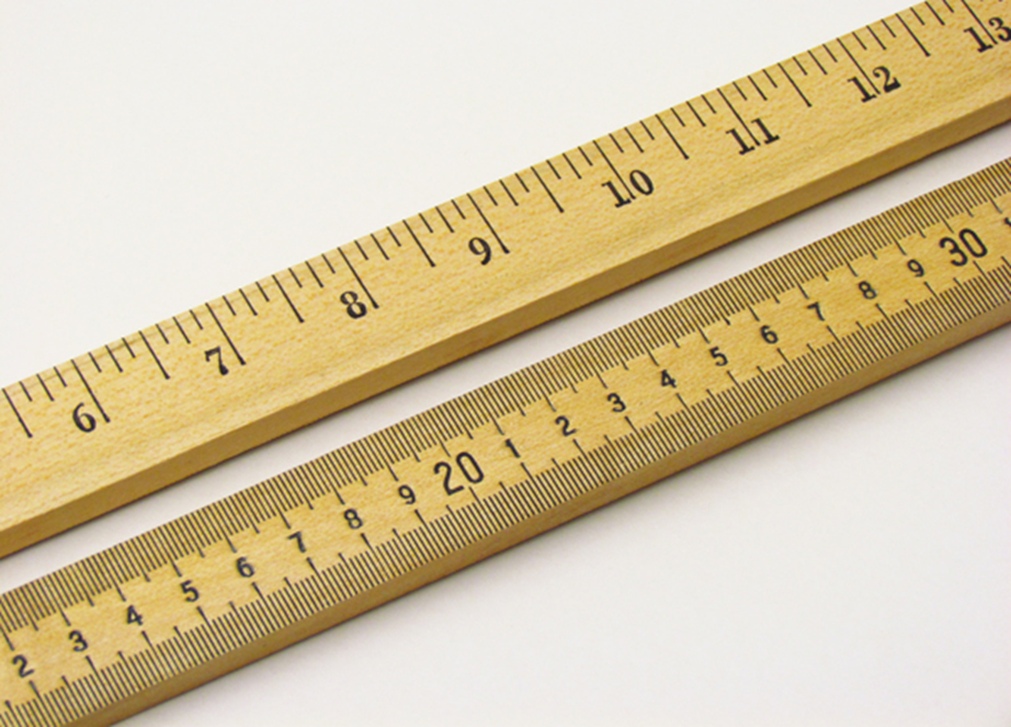
Metre rule
The metre rule can be measured shorter distances such as the length of a reading table
The metre rule is a standard instrument made of wood, steel or plastic. It is graduated in centimetres and millimetres so it can read to the nearest millimetre or 0.1cm
Vernier Calipers
Calipers generally are used to measure cylindrical objects e.g. diameter of a log of wood, pipes e.t.c where the metre rule cannot be used conveniently.
The Vernier caliper can measure smaller lengths such as the internal or external diameter of a tube or pipe, the depth of a cavity.
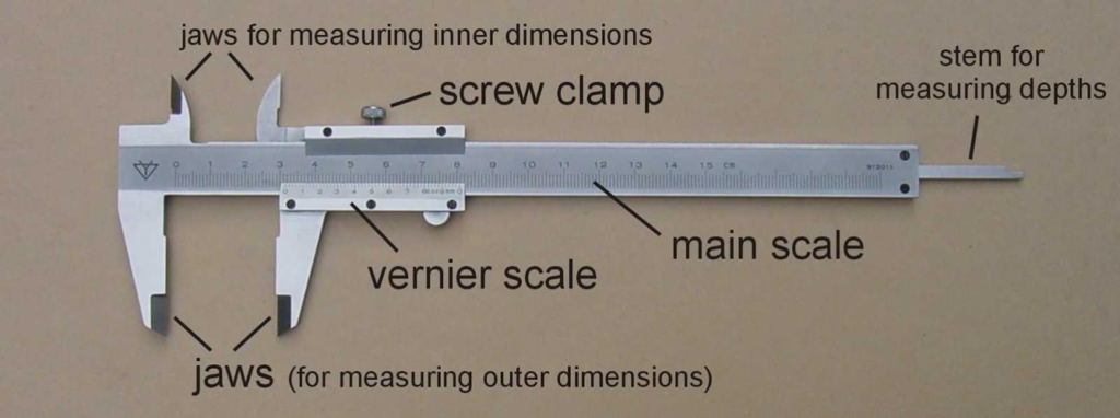
A Vernier caliper can measure to an accuracy of 0.01cm.
It has two scales: the main scale M with fixed jaws at one end and the Vernier scale V with moveable jaws.
The main scale is calibrated in millimetres like a metre rule.
The Vernier scale is constructed by dividing nine of the 0.1cm divisions into ten equal intervals so that each vernier division has a length of 0.09cm
When the zero of M coincides with the zero of V, then the length measured is zero
But as V slides on M, the readings on M and V together give the reading of the distance measured
How to read the vernier caliper
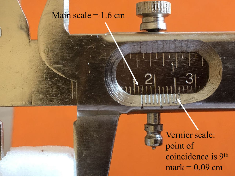
- Take the reading on the main scale that is just before the zero mark of the vernier scale i.e 1.6 cm
- Note the mark on the vernier that corresponds with the mark of the main scale and count how many marks from the zero mark of the vernier scale to this point of coincidence i.e. 9 marks. Each of these marks is 0.01 cm so the vernier reading is 0.09 cm
- Add the readings on the Main and Vernier scales
reading = (1.6 + 0.09) = 1.69 cm
Micrometer Screw Gauge
This instrument measure smaller lengths such as the diameter of a wire, thickness of paper or thin sheet of metal, diameter of a small pebble.
It has an accuracy of 0.001cm.
It consists of a main scale graduated in millimetres and a circular vernier scale which contains 50 divisions.
1 division is equivalent to 0.01mm (or 0.001cm)
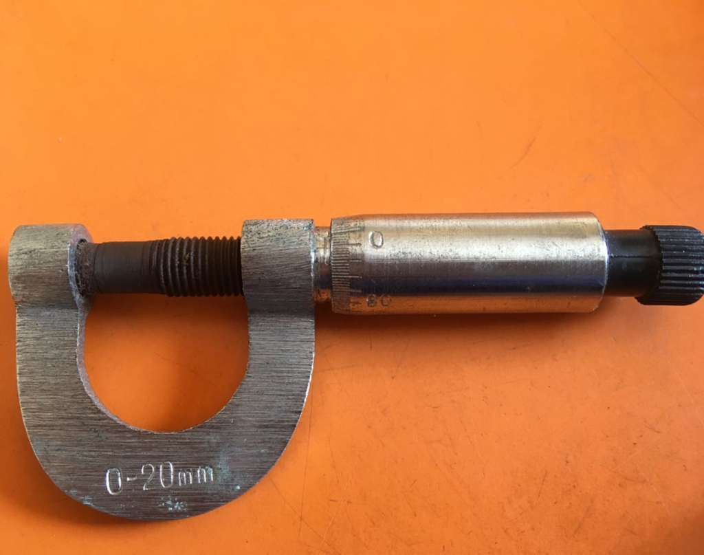
How to read the micrometer screw gauge
- Unscrew the gauge and place the object in between the anvil and the spindle and close the gap by screwing the instrument
- Record the reading on the main scale to the nearest decimal place e.g. 3.2mm
- Record the reading on the circular vernier scale e.g. 23 divisions or 0.23mm
- Add the readings 3.2 + 0.23 to get the complete reading is 3.43mm
Measurement of Time
Time measures the duration of an event. The SI unit of time is the second(s).
The instrument used to measure time in the laboratory is the stop clock or stop watch

The most natural time unit is the solar day. It takes the earth 1 solar day to complete one rotation about its axis
1 day = 24hours
1 hour = 60 minutes
1 minute = 60 seconds
Measurement of Mass
The mass of a body is the quantity of matter contained in it.
The SI unit of mass is kilogram (kg). It can be measured by
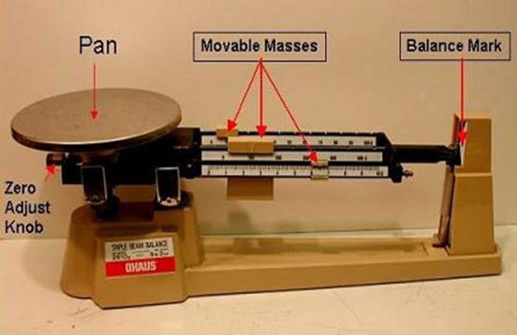
1. Beam balance (or weighing balance). It uses the principle of moments to measure mass
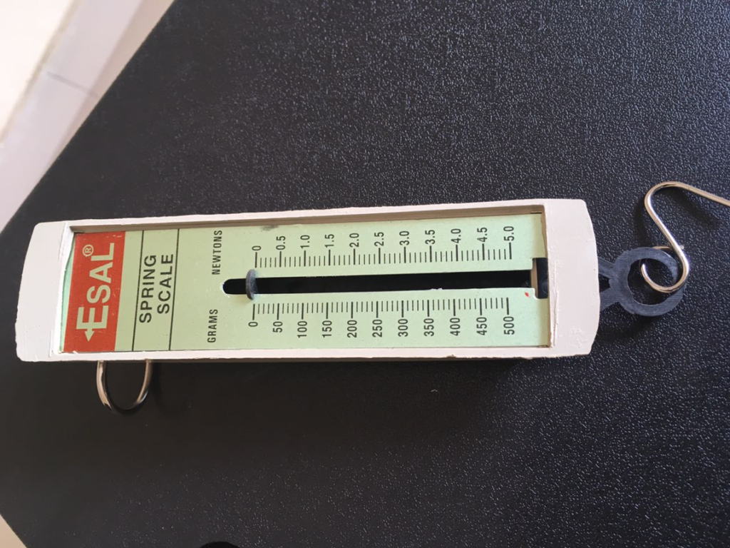
2.Spring balance. It uses the principle of elasticity to measure mass
Other instruments used to measure mass include lever balance, dial balance, direct reading balance
Mass and Weight
In general conversation, we talk of weight instead of mass, however, they are not the same in physics
| Mass | Weight |
|---|---|
| Mass is the quantity of matter in a body | Weight is a measure of the gravitational force or earth’s pull on a body |
| Mass is constant anywhere in the world | Weight varies from place to place. Its value is greater at the poles than at the equator |
| Mass is a scalar quantity | Weight is a vector quantity |
| Mass is measured in kilogram (kg) | Weight is measured in Newton (N) |
The weight of a body can be calculated using the relation
Weight(W) = mass(m) × acceleration due to gravity(g)
W=mg
The acceleration due to gravity of the earth is about 9.8ms-2. So, a mass of 65kg has a weight of approximately 650N
If for instance the body is taken to the moon where g=1.6ms-2, the mass is still 65kg but the weight is now 65 x 1.6 = 104N
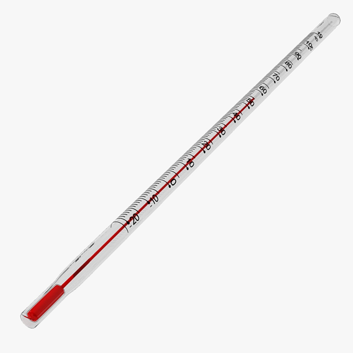
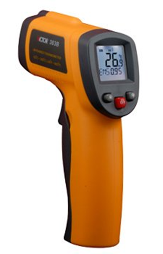
Measurement of Temperature
The device used to measure temperature is called a thermometer.
The figure below shows a laboratory thermometer
A clinical thermometer is used to mesure the body temperature

An infrared thermometer can measure the tempereature of a body without physical contact
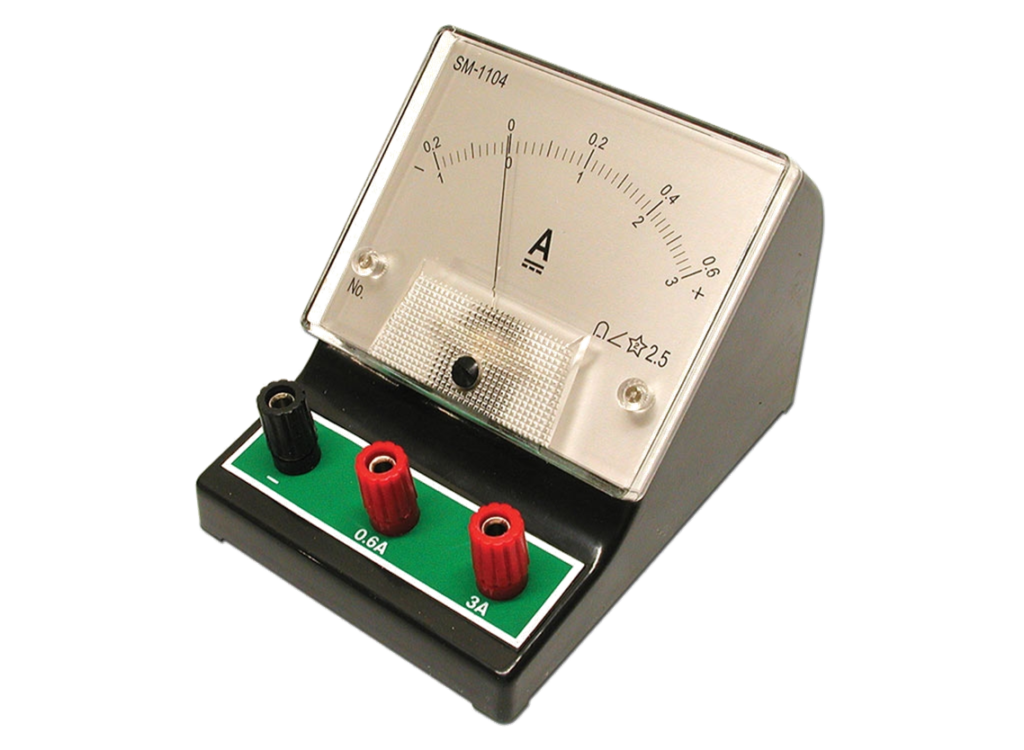
Measurement of Current
The device used for measuring current is called the ammeter.
Measurement of Volume
Volume of regular solids
A regular solid is one in which the shape conforms to a definite known shape i.e. A regular is any solid that has the shape of a cube, cuboid, cylinder, sphere, and so on.
For example, the volume can be measured by measuring the relevant lengths using appropriate instruments and applying the known formula for finding the volume of the shape.
The volume of a solid in the shape of a cylinder (e.g. coin, wire) can be obtained by measuring the diameter d of its cross-section and length l (or height h) with appropriate measuring instruments
and then applying the formula V = π (d2/4) h
or πr2h where r = d/2
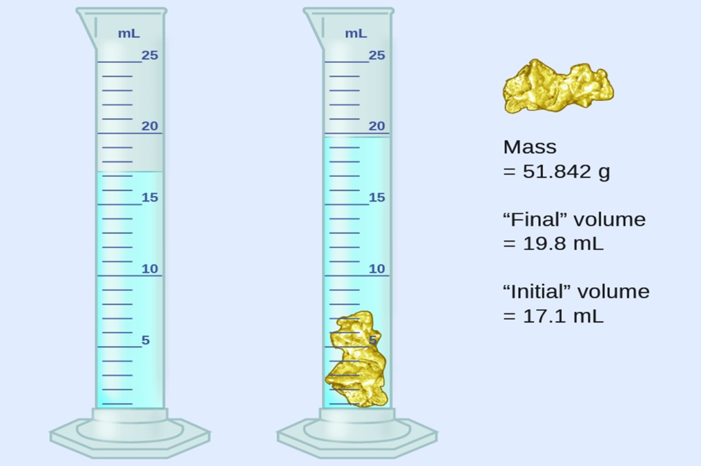
Volume of Irregular solids
An irregular is one that has no known shape, e.g stones, glass stopper, etc.
The volume is found by immersing it completely in a measuring cylinder containing a liquid in which the solid would not dissolve.
The volume of liquid displaced gives the volume of solid
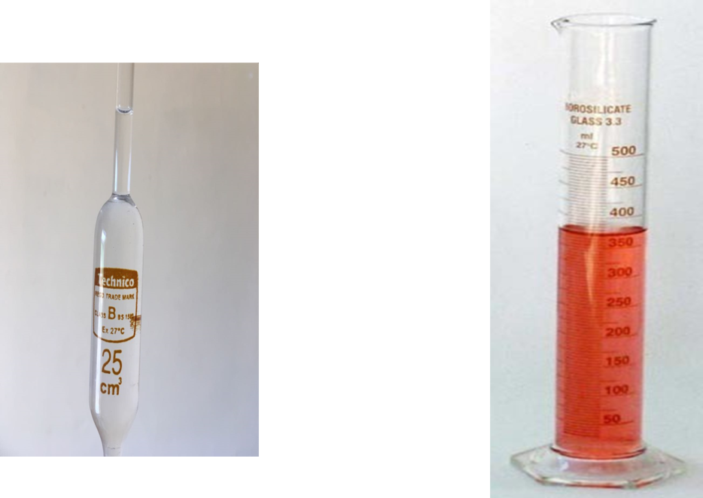
Volume of a Liquid
The volume of a liquid can be measured by the use of a measuring cylinder, a pipette or a burette
VECTORS
Physical quantities may be divided into two types:
a) Scalars
b) Vectors
A scalar quantity is one which has only magnitude, for example, distance, speed, temperature, volume etc.
A vector quantity is one which has magnitude as well as direction for example displacement, velocity, force etc.
Displacement is distance in a specified direction. A force is specified by stating its magnitude and its direction of its line of action. Weight which is a force acts vertically downwards
Scalar: the car travelled 5km (distance)
Vector: the car travelled 5km due north (displacement)
Scalars can be added and subtracted easily using ordinary algebra.
Vectors however are added and subtracted by other methods such as vector diagrams, scale drawing or parallelogram law of vector addition
Representation of a vector
A vector can be represented in magnitude by a given length of line and its direction by an arrow head at the end of the line.
It can be represented by a line at an angle to a reference plane (usually horizontal or vertical)

Addition of two vectors
Two or more vectors can be combined to give a single vector. This single vector is called resultant and can be defined properly as follows
The resultant of two or more vectors is a single vector that produces the same effect as the other vectors.
Let us consider the resultant of two vectors under the following conditions
CONDITION 1. IF THE VECTORS ARE IN THE SAME DIRECTION
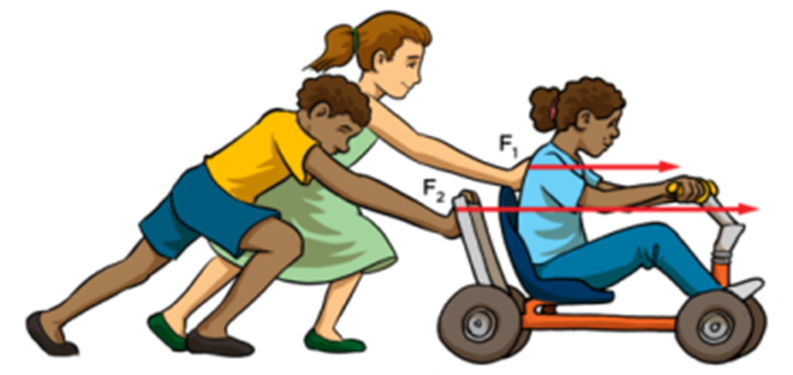
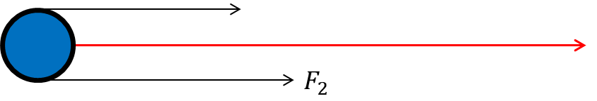
Consider two force vectors acting on a body in the same direction as shown.
The resultant R is given by
R = F1 + F2
And the direction is the same as that of F1 and F2
CONDITION 2. IF THE VECTORS ARE IN OPPOSITE DIRECTION
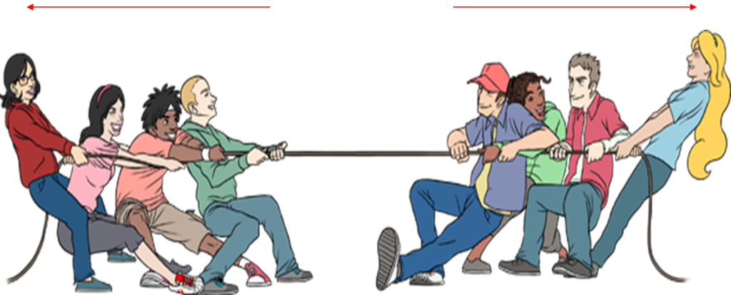

The resultant is given by
R = F2 – F1
the direction of the resultant is in the direction of the larger force (assuming F2)
CONDITION 3. IF THE VECTORS ARE AT RIGHT ANGLES TO EACH OTHER
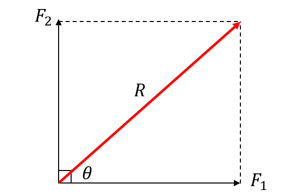
We complete the rectangle and use Pythagoras theorem
R2 = F12 + F22
R = √(F12 + F22)
To know the direction, we find θ i.e tan θ = F2/F1
Where θ = tan-1( F2/F1)
The direction is an angle θ to the F1 force
Parallelogram Law of Vector Addition
If two vectors are represented in magnitude and direction by the opposite sides of a parallelogram, the resultant is represented in magnitude and direction by the diagonal of the parallelogram drawn from the common point
The law is used for finding the resultant of two vectors when they are inclined at an angle θ other than a right angle
CONDITION 4. IF TWO VECTORS ARE INCLINED AT AN ANGLE θ
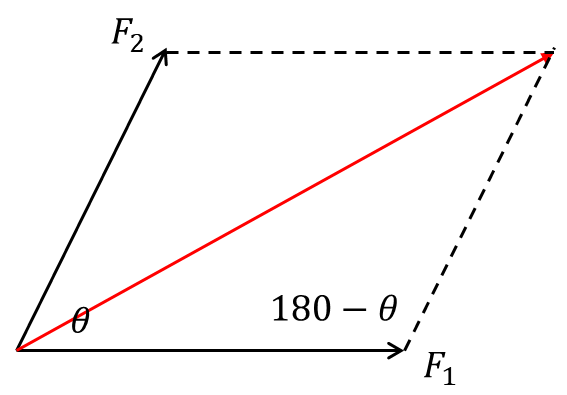
We use cosine rule to find the resultant
R2 = F12 + F22 – 2F1F2 cos (180 – θ)
The direction of the resultant is angle α, the angle the resultant makes with F2
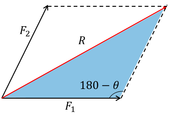
From sine rule: F2/sinα = R/sin(180-θ)
Resolution of a Vector
When a vector R acts at an angle θ to the positive Ox direction
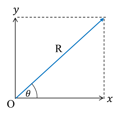
It can be resolved into the horizontal Ox direction and the vertical Oy direction by applying trigonometric ratios
sin θ = Ry/R vertical component Ry = R sinθ
cos θ = Rx/R horizontal component Rx = R cosθ
These two components will produce the same effect as the original vector R
Think of resolution as the opposite of resultant
This can easily be remembered by simply looking at the angle the vector makes with either the horizontal line or the vertical line.
If the vector R makes an angle θ with the horizontal, then the horizontal component is R cosθ and the vertical component is the “opposite” R sinθ.
If it makes an angle θ with the vertical, then the vertical component is R cosθ and the horizontal component is R sin θ.
Resultant of two or more vectors
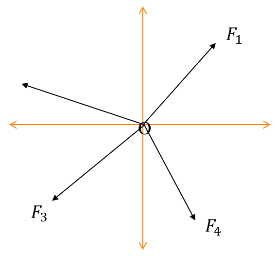
To find the resultant of several forces F1, F2, F3, F4, … acting at a point O, we first reduce the whole system to two perpendicular forces and then find the resultant using Pythagoras theorem
Example: Determine the resultant and direction of the forces acting at a point O as shown below.

When solving questions like this, take notice of the direction and the angle of the horizontal or vertical
Let us consider the vertical components first
Sum of vertical components ∑ Fy : 10 + 20 sin30 + (-3) + (-5 sin60)
Notice that the 10N, 20N, 3N and 5N have vertical components. The 10N and 3N are purely vertical forces. The 8N force has no vertical component, it is purely horizontal.
∑ Fy = 10 + 10 – 3 – 4.33
∑ Fy = Ry = 12.67N
Sum of horizontal components ∑ Fx = 20 cos30 + 8 – 5 cos60
∑ Fx = Rx = 22.82N

R = √(12.672 + 22.822)
R = 26N
Direction of R; θ = tan-1(Ry/Rx)
θ = tan-1(12.67/22.82) = tan-1(0.5552)
θ = 200
Relative Motion
Relative motion is comparing the motion of two bodies with reference to a point.
If two bodies A and B are moving in a straight line, the velocity of A (VA) relative to B (VB) is found by VA – VB
If A and B are moving in opposite directions, the relative velocity of A to B is VA + VB
Example: A car travelling at 120kmhr-1 overtakes a bus travelling at 80kmhr-1 in the same direction. What is the relative velocity of the car to the bus
The relative velocity of the car to the bus OR the velocity of the car relative to the bus is
100 – 60 = 40kmhr-1
MOTION
Whenever an object changes position, motion is said to have taken place.
Types of motion
A force is a pull or push motion
Motion is caused by a force.
There are 4 types of motion
1.Straight line motion e.g. a book sliding down an inclined table
2.To and fro motion: e.g. a simple pendulum
3.Rotational or circular motion e.g. blades of a fan
4.Random motion e.g. the motion of dust particles
Types of forces
Contact forces: this is a force that needs to touch the body before it is felt. For example: push, pull, friction, reaction, upthrust, air resistance
Non-contact forces: this force need not touch the body before its effect is felt. For example: gravity, magnetic, electrostatic
A force field is a region of space where a body experiences a force
Parameters of motion
1.Displacement (s): this is distance travelled in a specified direction. It is measured in metres (m)
2.Velocity (v): it is the displacement divided by time taken. Unit is m/s. This is speed in a specified direction Acceleration (a): it is the change of velocity divided by time taken. Unit is m/s^2
Terms used to describe motion
Displacement, velocity, acceleration
Displacement means distance moved in a specified direction. It is measured in metres (m)
Velocity/speed is change in displacement/distance within a given time. The unit is m/s speed=(distance moved)/(time taken)
Terms used to describe motion
Displacement, velocity, acceleration
Displacement means distance moved in a specified direction. It is measured in metres (m)
Velocity/speed is change in displacement/distance within a given time. The unit is m/s
speed=(distance moved)/(time taken)
Acceleration is the change in velocity with respect to time. The unit is m/s^2
acceleration=(change in velocity)/(time taken)
A bus increases its velocity from 30m/s to 90m/s in 12s. What is the acceleration of the bus?
acceleration=(change in velocity)/(time taken)=(90-30)/12=60/12 =5m/s^2
Equations of motion
Motion under gravity
A body falling under the influence of gravity has an acceleration due to gravity(g). This type of motion is a typical example of uniformly accelerated motion provided air resistance is neglected.
It was initially thought that bodies falling under the action of gravity alone fall at different rates; a heavy body will fall faster than a light body.
This acceleration due to gravity(g) acts downwards and is constant with a value of g=9.8ms^(-2) (“approximately” 10ms^(-2)). So when discussing motion under gravity or vertical motion, the following points should be noted.
I.If the motion is upwards, it is going against gravity and g=-ve but if the motion is downward, it is going with gravity and =+ve
II.If the body is projected vertically upward, at maximum height (Hmax) there is a momentary stop and v=0 at maximum height.
III.If the body is dropped from a height, then u=0. thus we write the equations of motion under gravity from the standard equations of motion given earlier
v=u+at ⇒ v=u±gt
v^2=u^2+2as ⇒ v^2=u^2±2gH s=ut+1/2 at^2 ⇒ H=ut±1/2 gt^2
So in vertical projection; at maximum height
v=0, a=-g, s=H_max, and v^2=u^2+2as becomes
0=u^2-2gH ⇒H_max=u^2/2g
Time to reach maximum height; 0=u-t⇒t=u/g
The total time of flight T is the time taken for the body to reach the ground again. This is twice the time it takes for the body to reach maximum height
T=2t⇒T=2u/g
If the body is falling from a height H above the ground
u=0, a=+g, s=H and s=ut+1/2 at^2 becomes
H=1/2 gt^2
2H=gt^2
t=√(2H/g)
Example: a ball is thrown vertically upwards from the ground with a velocity of 40ms^(-1). Calculate
i)The maximum height reached
ii)The time to reach maximum height
iii)The time of flight
u=40ms^(-1),a=-g=-10ms^(-2), s=H_m, v=0
i) “From” v^2=u^2+2as, 0=40^2-2(10) H_m
20H_m=1600
H_m=1600/20=80m
ii) From v=u+at, 0=40-10t
t=40/10=4s
(iii) Time of flight T=2×4=8s
Example: A ball is released from a height of 20m. Calculate i) the time it takes to fall ii) the velocity with which it hits the ground
s=H=20m, a=+g=10ms^(-2), u=0, t=?
i) From s=ut+1/2 at^2⇒20=0+1/2.10.t^2
20=5t^2, t^2=20/5=4
t=√4=2s
ii) From v^2=u^2+2as
v^2=0+2(10(20)
v=√400=20ms^(-1)
Projectile Motion
When an object is projected (or thrown) into space at angle of θ to the horizontal, it traces out a curved path. Many examples of projectile motion exist in our daily life
i)A stone shot out of a catapult traces out a curved or parabolic path *show video*
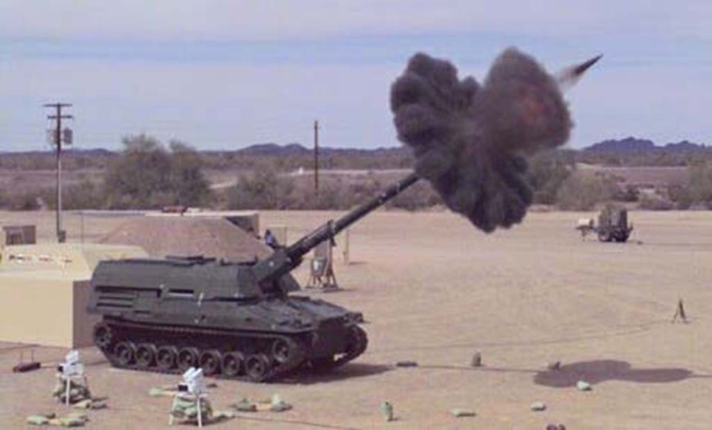
ii)Bullets or shells shot from guns *animate*
iii)The motion of a ball from a free kick in football, or throw of discuss, javelin or shotput *show video*
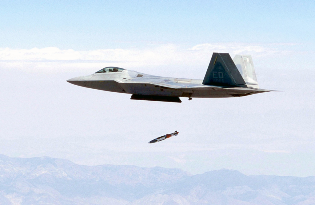
iv)The missile from a fighter jet to hit a target on the ground
The object that moves through space is called a projectile and the curved path it follows is the trajectory.
Any projectile performs two independent motion
1.A constant or uniform horizontal motion
2.A vertically downward acceleration under the influence of gravity
If a ball is dropped from a height and another ball is thrown horizontally from the same height at the same time, they will both strike the ground at the same time. This is because the acceleration of both bodies is vertical and is independent of the horizontal velocity.
Terms used in describing a projectile
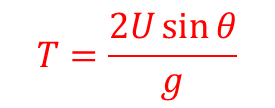
1.Time of flight (T) is the time taken for the projectile to return to the ground or the same horizontal level from which it was projected.
●
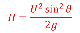
2.Maximum height (H) is the highest vertical distance reached by the body.
●
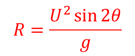
3.Range (R) is the horizontal distance covered from the point of projectile to the point it strikes the ground again or reaches the same horizontal level.
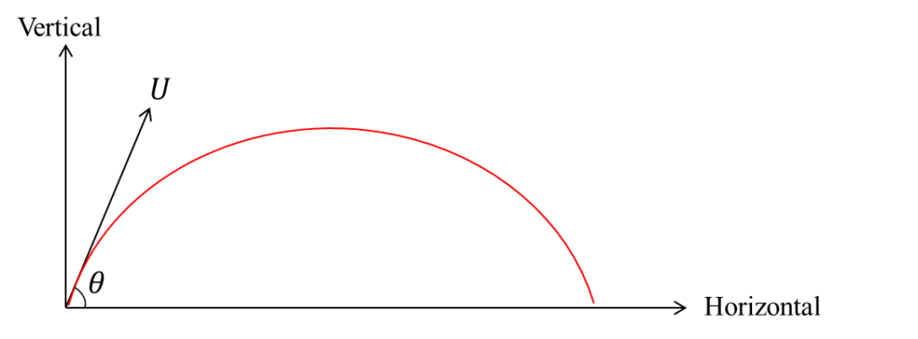
To calculate these parameters, we need the initial velocity U and the angle of projection θ (usually measured from the horizontal)
We resolve this initial velocity U into horizontal and vertical component
Horizontal component = U cosθ
Vertical component = U sinθ
The horizontal component is usually unaffected by the vertical acceleration of free fall at maximum height. The vertical component of t he speed is zero i.e. v=0
And from the equation of motion
v=u+at
v=0, u=U sinθ, a=-g,
t=”time to reach” “max.” ”height”
0=U sinθ-gt⇒t=(U sinθ)/g
The time taken to rise from the point of projection on the ground to the maximum height is equal to the time to fall from maximum height to ground level.
∴”time of flight ” T=2t
Next is to find the maximum height
From v^2=u^2+2as
v=0, u=U sinθ, a=-g, s=H
0=(U sinθ )^2-2gH⇒2gH=U^2 sin^2θ
To determine the range R, we use the horizontal component of velocity i.e. Ucosθ
From s=ut+1/2 at^2
s=R, u=U cosθ, a=0 “(since there is no horizontal acceleration)”
Then R=U cosθ.t+0
But t=time of flight=(2U sinθ)/g
R=U cosθ.(2U sinθ)/g=(2U^2 sinθ cosθ)/g
From trigonometric identities, 2 sinθ cosθ≡sin2θ
The maximum range (farthest horizontal distance) a projectile can attain is when the angle of projection is 450.
Then sin2θ=sin〖(2×45)=sin90 〗


Applications of projectiles
Projectile has a wide range of application in science and technology, sports and warfare.
In science and technology
In sports
1.Kicking of football in air
2.Throwing of basketball, also throwing of discus, shot-put and javelin
In warfare
1.Shooting of arrows, spears or canon balls
2.Launching of missiles from fighter jets or from ground
Simple Harmonic Motion (SHM)
This is a type of periodic motion that occurs very frequently in physics.
It is defined as the to and fro motion of a body whose acceleration is directed towards a fixed point (or equilibrium position) and is proportional to its displacement from the point.
Example of simple harmonic motion
WORK, ENERGY & POWER
WORK
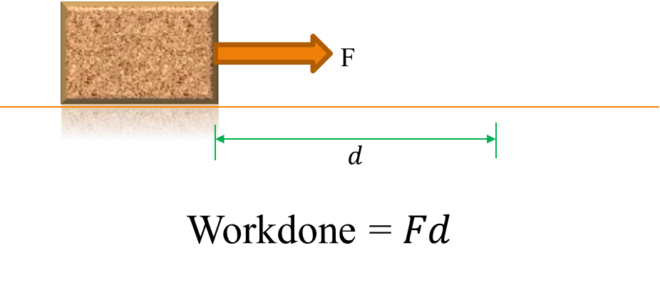
Work is defined as the product of force and distance moved in the direction of the force.
In ordinary conversation though, work may mean school activity, farm or office work.
Work is done when a person pushes a car and it moves a certain distance or a body is raised through a height. Thus,
“Workdone(” W”) = Force” (F)” × distance moved in the direction of the force(” d”)”
W=Fd
The unit of workdone is Joules (J)
An inclined force may move a body horizontally.
In such cases, the force must be resolved along the direction of movement of the body
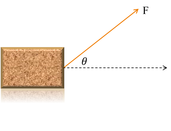
W=F cosθ × d
Example: A car is pushed along a straight road by a force of 500N. Calculate the workdone in moving the body a distance of 20m.
W = F × d, F=500N, d=20m
W = 500 × 20
= 10 000J OR 10 KJ
Work is also done when a body moves through a height. In earth’s gravitational field, there is always a force pulling a body towards the earth’s centre. The weight of the body is the force and the height is the distance moved
Force = Weight = mg
Where m is the mass of the body and g is the acceleration due to gravity
And since Workdone = Force × distance
Workdone = mg × h
W = mgh
Example: A stone of mass 15kg falls through a height of 20m. Calculate the workdone.
[Take g = 10ms-2]
W = mgh, m = 15kg, h = 20m
W = 15 × 10 × 20
W=3000J
Example: A load of mass m slides down a smooth plane inclined at θ to the horizontal from a point A to B. The same mass is the dropped from A to the ground C, a vertical distance h. In which of the two situation is more work done?
*
The force is the weight of the body acting downwards which is mg
From A to C, the workdone is mgh
From A to B, the workdone is mg×AB sinθ.
The inclined distance AB is not in the same direction as the vertical downward force mg. So we must resolve the inclined distance and find its corresponding vertical distance. sinθ=AC/AB
The corresponding vertical distance is AC=AB sinθ and workdone =mg×AC= mgh
Hence the same work is done in both cases.
Generally, workdone by gravity depends only on the vertical distance moved irrespective of the path taken
ENERGY
Energy is the ability or capacity to do work.
The SI unit is also Joules (J)
A great deal of energy is required to do most human activities.
A car needs to have fuel (energy) before setting out on a journey (work). A player needs to eat food (energy) before playing football (work).
The world depends basically on energy resources for industrial, computer, science and technological developments.
These resources are of two types:
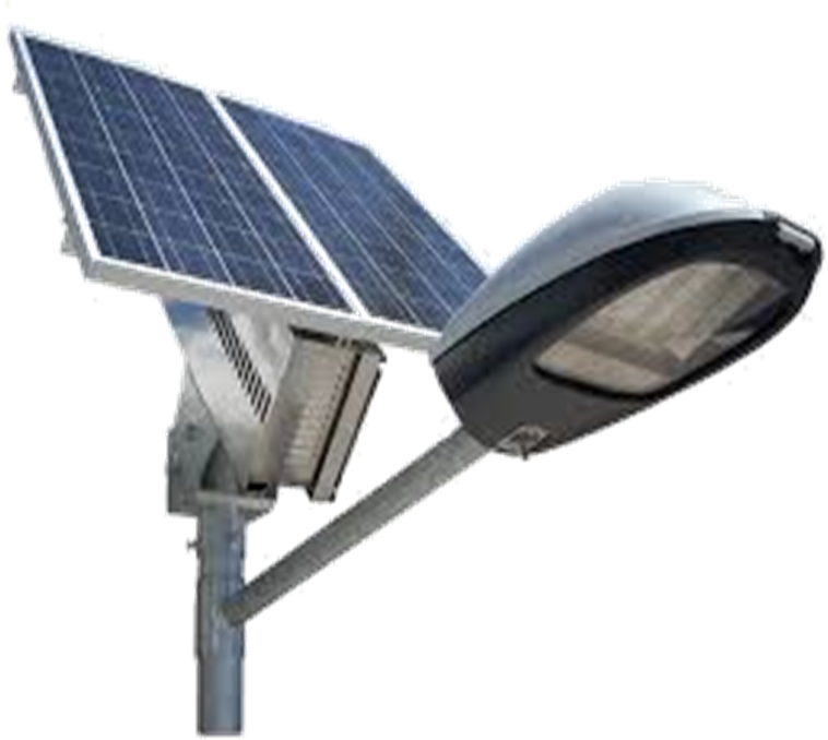
1. Renewable resources
These resources are inexhaustible i.e they do not finish e.g. sun that produces solar energy, wind that gives wind energy. Hydro (water falls) that produces hydroelectricity etc.
2. Non-renewable resources
These are exhaustible resources e.g. petroleum that produces kerosene, petrol or cooking gas, coal or nuclear resources that can be used to generate electricity, food eaten by man produces energy for activities such as reading, playing, farming etc.
Forms of energy
a) Solar energy from the sun, used in solar cells
b) Chemical energy from batteries or food

c) Wind energy from wind used in windmills

d) Electrical energy from electricity used in driving our fans, running refrigerator, television and lighting our homes and environment.

e) Heat energy from hot objects used in heaters.
f) Mechanical energy from moving objects.
g) Sound energy from loudspeakers or bells.
h) Nuclear energy developed from radioactive substances such as Uranium.
i) Elastic energy such as that stored in a spring
Transformation and conservation of energy
The forms of energy listed previously can be transformed or converted from one form to another by suitable machines.
Some examples are
a) The generator (dynamo) converts mechanical energy to electrical energy. A motor does the reverse (i.e. from electrical energy to mechanical energy)
b) The telephone converts sound energy to electrical and back to sound
c) The loudspeaker converts electrical energy to sound energy. The microphone does the reverse
d) When the brakes of a car are applied, the mechanical energy original possessed by the car is converted to heat energy in the tyres and some sound energy.
The principle of conservation of energy states that energy can neither be created or destroyed but can be converted from one form to another.
MECHANICAL ENERGY
A body can possess mechanical energy by virtue of its position or motion.
For example, a car possesses mechanical energy due to its motion and a stone held at a height above the ground possesses mechanical energy due to its position.
The former type of mechanical energy is called kinetic energy and the latter is referred to as potential energy.
Kinetic energy is the energy possessed by a body in motion. The kinetic energy(K.E.) of a body of mass m moving with a velocity v is given by
K.E.=1/2 mv2
Potential energy is the energy possessed by a body by virtue of its position.
A body held at a height h above the ground has potential energy
P.E=mgh
This potential is sometimes referred to as gravitational potential energy.
Examples:
1) A bullet of mass 50g is moving with a speed of 144km/hr. Calculate its kinetic energy.
2) A brick of mass 12kg released from a height of 20m. With what energy does it strike the ground (take g=10ms-2).
m=50g OR 50/1000 kg=0.05kg,
v=144km/hr=144/1×1000m/(60×60s) =40ms-1)
K.E.=1/2 mv2=1/2×0.05×402=40J
2) The potential energy of the brick is mgh
m=12kg, g=10ms-2, h=20m
P.E.=12×10×20
=2400J or 2.4 kJ
This energy is converted to kinetic energy when it strikes the ground.
Conservation of Mechanical Energy
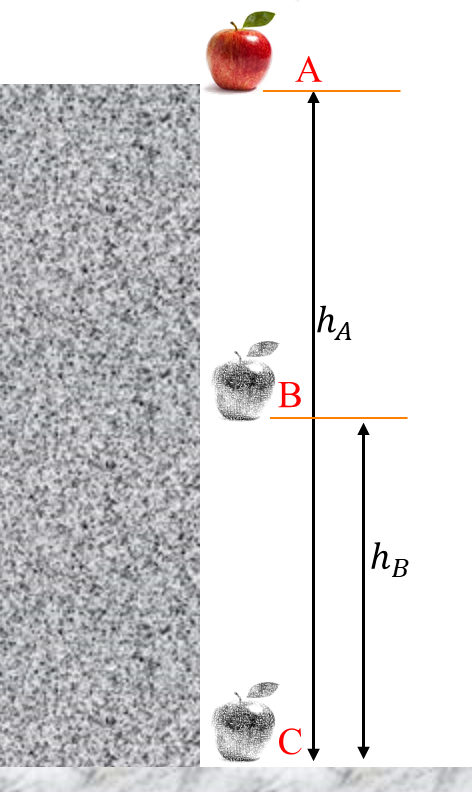
Consider a falling object initially at a height hA. It possesses only potential energy = mghA
After falling to position B, the total energy possessed is the sum of the potential energy at height hB and the kinetic energy
i.e. total energy at position B = mghB + 1/2 mvB2
Just before the body strikes the ground, at position C, the body possesses only kinetic energy as all the potential energy at position A has been converted to kinetic energy = 1/2 mvC2
Thus by the principle of conservation of energy,
K.E.+ P.E. = constant at all points
If the velocity of the body just before hitting the ground is v. Loss in P.E. at A is equal to gain in K.E. at C i.e.
mgh = 1/2 mv2
2gh=v2
v=√2gh
Example: A stone of mass 5kg is dropped from a height of 30m. Calculate
i) the potential energy at this height
ii) The kinetic energy of the body just before it strikes the ground
iii) The velocity of impact [take g=10ms-2]
m = 5kg, h = 30m
i) P.E. = mgh = 5 × 10 × 30 = 1500J
ii) K.E. before hitting the ground = initial maximum potential energy
K.E. = 1500 J
iii) v = √2gh = √(2 × 10 × 30) = √600 = 24.5ms-1
A simple pendulum alternates potential and kinetic energy
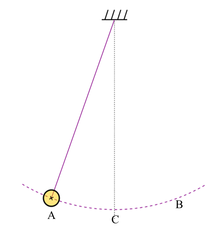
At the furthest point (A and B), the pendulum is momentarily still and has no kinetic energy, but maximum potential energy since it is at its highest point.
At point C, its lowest point, there is no potential energy, but it is moving the fastest and has maximum kinetic energy.
The velocity at this point is also given as v=√2gh
Example: A body of mass 3kg falls from rest through a height of 25m. It comes to rest after penetrating a distance of 0.5m into the ground. Calculate the average force exerted by the sand in bringing the body to rest. (Take g=10ms-2)
m = 3kg, h = 25m
Loss in P.E is converted to gain in K.E. and
P.E. = K.E. = 3 × 25 × 10 = 750J
This K.E. is converted into workdone by the sandy ground in penetration through a distance 0.5m by an average force F
∴750 = F × 0.5
F = 750/0.5 = 1500N
Example: A ball of mass 4kg is dropped of 30m above the ground. Determine the velocity of the ball when it is 18m above the ground. [take g = 10ms-2]
At 30m, P.E = mgh, m = 4kg, h = 30m
P.E.= 4 × 10 × 30 = 1200J
At 18m, total energy = mgh18 + 1/2 mv182
1200 = (4 × 10 × 18) + (1/2 × 4 × v182)
1200 = 720 + 2v182
2v182 = 480
v182 = 480/2 = 240
v18 = √240 = 15.5ms-1
POWER
Power is defined as the rate of doing work OR workdone per unit time.

The unit of power is watts (W)
P = (F×d)/t
P = F × v
Example: Compute the power output in watts of a machine that lifts 50kg crate through a height of 0.4m in 1 minute. [Take g = 10ms-2]
m=50kg, weight = mg = 50 × 10 = 500N
Distance = height = 0.4m, t = 1 minute = 60 seconds
Power = Workdone/(time taken) = (weight × height)/time
Power = (500×0.4)/60 = 3.33W
MACHINES
A machine is any device that is used to make work easier.
There are several types of machines
- Levers
- Pulleys
- Inclined plane
- Gears
Levers
A lever is a device that consists of three parts – the handle that produces the effort, the fulcrum (or support or pivot), and the load.
A lever is divided into 3 classes depending on the arrangement of the three partsfirst class levers: Here, the fulcrum is between the load and effort e.g. plier
First Class Levers
Here, the fulcrum is between the load and the effort

Second class levers: The load is between the fiulcrum and the effort


Third Class levers: The effort is between the fulcrum and the load

Gears

EQUILIBRUM OF FORCES
A body is said to be in equilibrium under a system of forces if it does not move or rotate.
This means that the resultant force on the body is zero.
Moment of a force
It has been established in the earlier chapter that a force is what causes a body to move. But if a body does not move under the action of several forces, it means that somehow the forces have canceled each other and the body is in equilibrium.
Apart from causing motion, a force also causes rotation or movement about a point. This rotation or turning effect is called moment
The moment of a force about a point is defined as the product of the force and the perpendicular distance from the line of action of the force to the point.
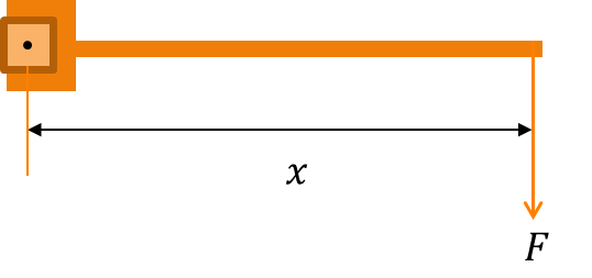
Moment = Fx
The unit of moment is Newton-metre (Nm)
If the force is inclined at an angle θ to the horizontal
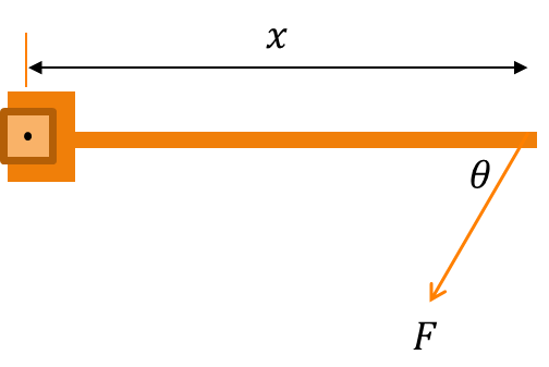
The moment M is given by
M = F sinθ × x
The point at which the moment acts is the pivot or support or fulcrum.
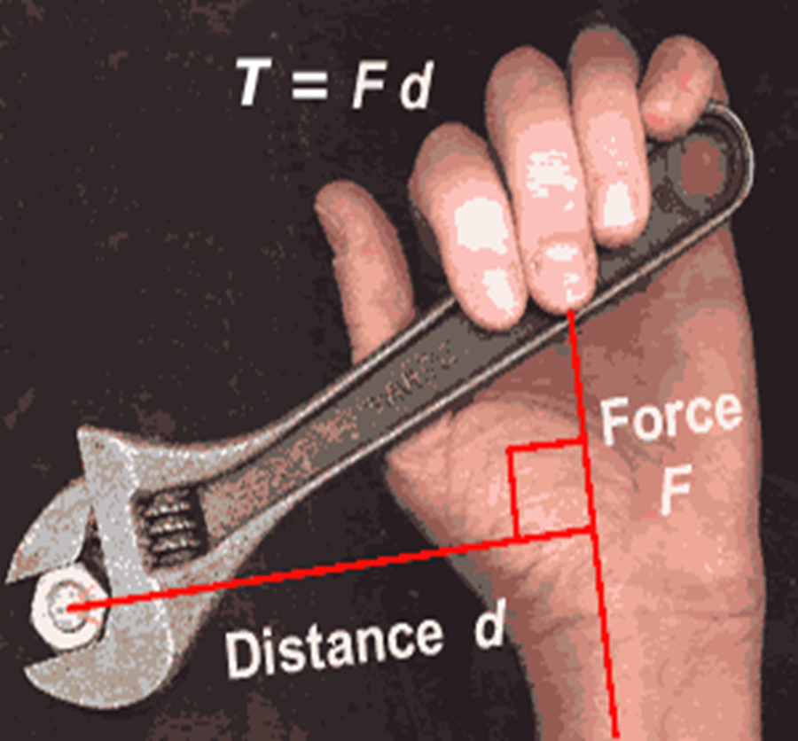
A large moment can be produced with a small force and a large distance. This is why it is easier to loosen a nut with a long spanner than a short one because a small effort is applied in the former
COUPLE
A couple is a system of two parallel and equal but opposite forces that do not act on the same line.
A couple is seen in the action of turning a water tap on or off. Equal and opposite forces are applied by the thumb and first finger
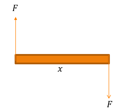
The moment of a couple is defined as the product of one of the forces and the perpendicular distance between the forces
Moment = Fx
Equilibrium of Parallel Forces
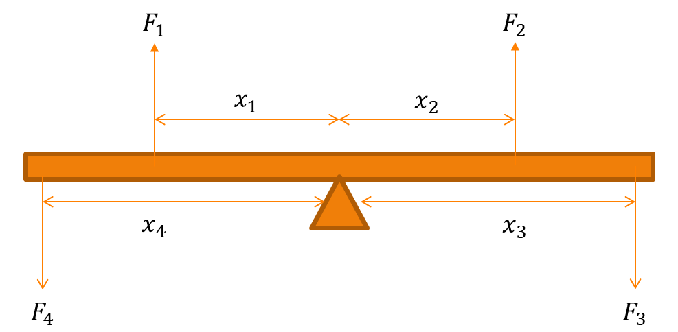
For a body to be in equilibrium under a system of parallel, coplanar forces, the following conditions must be satisfied
- The resultant of all the forces must be zero i.e. the sum of upward forces must be equal to the sum of downward forces. Condition 1: F1 + F2 = F3 + F4
- The algebraic sum of the moments must be zero i.e. the sum of clockwise moment about a point must be equal to the sum of anticlockwise moment about the same point.
This is also called the principle of moments
Clockwise moment: F2 x2 + F3 x3
Anticlockwise moment: F1 x1 + F4 x4
Condition 2: F2 x2 + F3 x3 = F1 x1 + F4 x4
Example: A light (weightless) bar is pivoted at the centre and weights of 5N and 10N placed 3m and 2m respectively from the pivot on one side are balanced by a weight of 20N on the other side. How far is the 20N weight from the pivot?
The diagram is shown. Let the distance of the 20N weight from the pivot be x
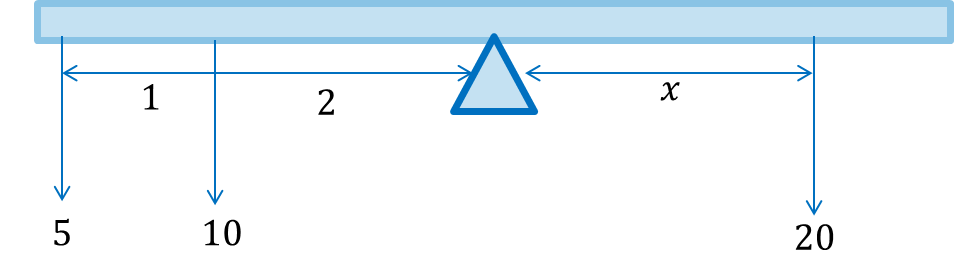
The 5N and 10N force produce anticlockwise moment about the pivot
(5 × 3) + (10 × 2) = 15 + 20 = 35Nm
The 20N force produces clockwise moment about pivot: 20 × x
At equilibrium, clockwise moment = anticlockwise moment (condition 2)
35 = 20x
x = 35/20 = 1.75m
Centre of Gravity
The centre of gravity of a body is defined as the point through which the resultant weight acts.
The position of the centre of gravity depends on the shape of the body. If a body is supported at the centre of gravity, it will remain stable.
We can determine the centre of gravity of regular and irregular shapes.
A. Regular shapes
| Types of shapes | Position of centre of gravity |
|---|---|
| Circular object e.g. disc | Centre of the circle |
| Square, rectangle, parallelogram | The point of intersection of the diagonals |
| Triangle | The point of intersection of the lines bisecting the angles |
| Uniform rod e.g. metre rule | Midpoint of the rod i.e. the 50cm mark in the case of a metre rule |
B. Irregular shapes
The position of the centre of gravity of irregular shapes can be found by two common methods
i) Plumbline method: A plumbline consists of a small lead bob supported by a thin cord.
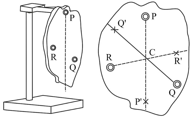
For example, to determine the centre of gravity of an irregular plane sheet of material: make two holes in the material at any two points P and Q close to the edges of the sheet of material and suspend the material and plumbline from a rigid support. Draw the lines PP1 and QQ1.
The centre of gravity is the point of intersection of the lines
ii) Balancing method: the object is balanced on a knife edge and a vertical line is drawn on the object from this balance point. The line of balance is used to find the centre of gravity.
The position of the centre of gravity of a uniform rod or metre rule can be found using this method.
TYPES OF EQUILIBRIUM
1. Stable Equilibrium
A body is in stable equilibrium if when slightly tilted or given a slight displacement, it returns to its original position e.g. a cone or funnel resting on its circular base
If the body has a low centre of gravity and a wide base, it will remain in stable equilibrium. E.g. a car
2. Unstable Equilibrium
If the body receives a slight displacement (push), it topples over e.g. a cone resting on its small pointed end, an egg standing on its pointed end.
If the body has a high centre of gravity and a small or narrow base, it is in a state of unstable equilibrum.
3. Neutral Equilibrium
When the body receives a slight displacement, it tends to come to rest in a new position e.g. a cone or funnel resting on its curved surface, a ball or orange rolling on a surface.
The position of the centre of gravity remains unchanged when it moves to a new position
Equilibrium of non-parallel forces
The conditions for equilibrium for a body under non-parallel forces may be stated as follows
1. The algebraic sum of the horizontal components of the forces must be zero i.e. ∑ Fx = 0
2. The algebraic sum of the vertical components equals zero ∑ Fy = 0
Example: Three forces act at pint O in the figure below. If the point O is in equilibrium, find the values of P and Q.

Horizontal component: 10√3 – P cos 300
= 010√3 = P × √3/2
P = (2 × 10√3)/√3 = 20N
Vertical components: Q – P sin30 = 0
But P = 20N, then Q – 20 sin30 = 0
Q = 20 sin 30 = 10N
DENSITY and PRESSURE
The density of a substance is defined as the ratio of its mass to its volume i.e. the mass per unit volume
density = mass /volume
We use the Greek letter ‘rho’ (ρ) to represent density. If the mass is represented by m and the volume V, then
ρ = m/V
The S.I. unit of density is kgm-3 (kilogram per metre cube)
Sometime gcm-3 is used as a unit in laboratory work
1000 kgm-3 = 1 gcm-3
The conversion to kgm-3 is achieved by multiplying the density in gcm-3 by 1000
Example: A block of wood of density 0.6 gcm-3 has a mass of 120g. Calculate the volume of the block.
from ρ = m/V, 0.6 = 120/V
V = 120/0.6 = 200 cm3
Density of some common substances
| Substance | Density (×1000 kgm-3) |
|---|---|
| Gold | 19.3 |
| Aluminium | 2.7 |
| Brass | 8.9 |
| Lead | 11.3 |
| Mercury | 13.6 |
| Water | 1 |
| Paraffin(kerosene) | 0.8 |
| Petrol | 0.7 |
| Glass(varies) | 2.6 |
| Air | 0.0013 |
Relative Density
It is the density of a substance compared with the density of water.
Water is used for comparing the densities of other substances. The relative density (r.d.) is defined as follows
r.d. = density of substance/density of water
r.d. = mass of substance / mass of equal volume of water
and similarly = weight of substance / weight of equal volume of water
The density of water is 1000kgm-3 (or 1gcm-3). Relative density has no units.
The relative density of a substance is the same magnitude of the density of the substance in gcm-3 (but without the units).
The density of mercury is 13600kgm-3 and its relative density is 13.6. The relative density of water is 1.
Determination of density of a solid
The determination of density of a solid substance involves determining its mass by means of a chemical balance or spring balance and thereafter determine its volume.
The shape of a solid may be regular or irregular.
By finding the ratio of the mass to its volume, we obtain the density of the solid.
1) Regular solid
The volume of a regular solid e.g. cube, cylinder can be found by measuring the dimensions by means of a vernier calliper or micrometer screw guage and the formula for the volume of the solid is applied.
The solid is thereafter weighed on a chemical balance to find its mass.
Example: Find the density of the material of a solid sphere of radius 35mm and has a mass of 1.5kg.
Vol. of sphere, V = 4/3 πr3
r = 35mm = 35/1000 m
V = 4/3 × 3.14 × (0.035)3
V = 0.0001795 m3
ρ = m/V = 1.5/0.0001795 = 8356 kgm-3
2) Irregular solid
The mass is obtained by direct weighing.
The volume is found by immersing the body in water in a measuring cylinder or a displacement. The body should not be a floating body and not soluble (will not dissolve in water).
The rise in volume measured from the measuring cylinder is the volume of the solid.
The density is again calculated by dividing its mass by the rise in volume in the cylinder.
Determination of relative density of a liquid
A relative density bottle can be used to find the density of a liquid. This is essentially a glass bottle that can be covered properly.
The relative density bottle is weighed empty first and has a mass m.
It is then filled with liquid and weighed ml.
Finally, it is emptied, cleaned and refilled with water and weighed. This is mass mw.
From r.d.= mass of substance / mass of equal volume of water

Example: An empty relative density bottle weighs 25g. It weighs 65g when filled with a liquid and 75g when filled with water. Calculate the density of the liquid.

Upthrust
It is common experience that when a heavy object is in water, it becomes lighter. This is noticed when a bucket of water is being drawn out of a well.
The bucket appears very light when it is still under water but becomes very heavy as soon as it is out of water.
This loss in weight is called Upthrust.
Upthrust is the loss in weight experienced by a body when it is completely or partially immersed in a fluid (liquid or gas).
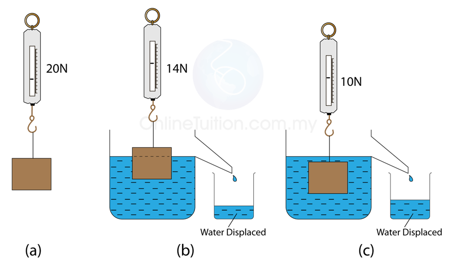
a) Object in air
b) Object partially immersed
c) Object fully immersed
If W is the object in air and T is the weight of object in water, then U is the upthrust given by
U = W – T = loss in weight
Archimedes’ Principle
This principle states that when a body is wholly or partially immersed in a fluid, the weight of fluid displaced is equal to the upthrust
Weight of fluid displaced = upthrust
Example: A solid weighs 0.09N in air and 0.03N in a liquid of density 800kgm-3. Calculate
i) upthrust of liquid on the solid
ii) volume of the solid
weight in air (W) = 0.09N, weight in liquid (T) = 0.03N
upthrust(U) = W – T = 0.09 – 0.03 = 0.06N
From Archimedes’ principle:
weight of liquid displaced = upthrust = 0.06N
This weight has a mass of 0.06/g = 0.06/10 = 0.006kg
ρ = m/V ⇒ 800 = 0.006/V
V = 0.006/800 = 7.5 × 10⁻⁶ m3
Volume of liquid displaced(V) = volume of solid
Volume of solid = 7.5 × 10⁻⁶ m3
Example: A spiral spring with a metal extends by 10.5cm in air. When the metal is fully submerged in water, the spring extends by 6.8cm. Calculate the relative density of the metal. (Assume Hooke’s law is obeyed) [WAEC’ 12]
F = ke [Hooke′s law]
e1 = 10.5 cm, e2 = 6.8 cm
F1 = 10.5 k
F2 = 6.8 k
R. density = weight in air / weight of equal vol. of water = F1/F2
r.d. = 10.5k/6.8k = 1.54
Determination of relative density of solid from Archimedes’ principle
We can find the density of a solid using Archimedes’ principle.
The solid is weighed in air (W) using a spring balance. It is then suspended and completely immersed in water and the reading on the spring balance is noted (Ww)
Upthrust = W-Ww = weight of water displaced

To find the relative density of a liquid using Archimedes principle
A solid is first weighed in air (W), then in water (Ww), and finally in the liquid (WL)
Weight of water displaced = W – Ww
Weight of liquid displaced = W – WL
Since the same solid is used, the volume remains the same and as such, the volume of water displaced is equal to the volume of liquid displaced.

Principle of Floatation
If a body is denser than a liquid it is placed on, the body sinks. A metal spoon sinks in water for example because the density of the metal is higher than the density of water. But when the density of a body is less than that of the liquid it is placed on, the body will sink until a point is reached when the weight of the liquid displaced is equal to the weight of the body. At this point, the body is in equilibrium and is said to be floating.
A body floats when the upthrust exerted upon it by the fluid (liquid or gas) is equal to the weight of the body. This is the principle of floatation.
A simpler way of stating this principle goes thus: A floating body displaces its own weight in a fluid in which it floats.
So the principle essentially states that if a body floats, the upthrust is equal to the weight
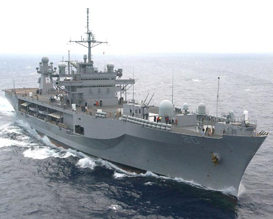
Applications of floatation
1. Ships even though they are made of steel still float in water. This is because they are hollow objects containing a large volume of air and the average density is less than that of water
2. A toy balloon that has not been inflated cannot float in air but once air has been blown into it, it begins to float.
3. A hot air balloon used in tourist centres is able to float upwards in air

4. Icebergs (huge chunks of ice) formed in the polar regions are floating in the sea

Hydrometer
The hydrometer is an instrument used for measuring the density of liquids.
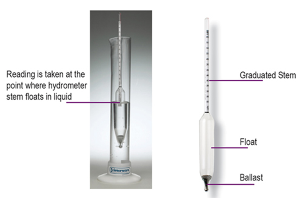
It is used in testing the concentration of acid in batteries. The acid in a fully charged cell should have a relative density of 1.25 and 1.15 if the cell has been discharged. This makes it more suitable than a voltmeter that would give the same e.m.f. reading irrespective of the state of charge of the battery.
The hydrometer is also used in testing milk, it is called a lactometer when used for this purpose
The sensitivity of a hydrometer is enhanced by ensuring that the stem is narrower.
Example: A block of wood of density 0.6gcm-3, weighing 3.06N in air, floats freely in a liquid of density 0.9gcm-3. Calculate the volume of the portion immersed. (g=10ms-2) [WAEC’ 12]
A floating body displaces its own weight in a liquid
Weight of liquid displaced = 3.06N
Mass of liquid displaced = 3.06/10 = 0.306kg OR 306g
Vol. of liquid displaced = (mass of liquid displaced)/(density of liquid)
= 306/0.9 = 340cm3
The volume of liquid displaced = volume of wood portion immersed = 340cm3
PRESSURE
Pressure is defined as the force acting perpendicular per unit area of surface.

The S.I. unit of pressure is Pascal (Pa) or Nm-2
From the above equation, if area(A) is very small, pressure will be large, and then when A is large, pressure will be small.
A woman wearing pointed heels shoes exerts more pressure on the ground than if she was wearing flat heels.
The area in the former is small, and so the pressure will be large.
The sharp point of a needle or knife pierces more easily even when a small force is applied because the area involved is small.
Example: A force of 80N acts on an area of 5m2. what is the pressure exerted on the surface?
Pressure(P) = F/A = 80/5 = 16 Nm-2
2) Calculate the least pressure exerted on a surface of rectangular block 3m × 4m × 5m by a weight of 200N.
Least pressure is obtained on maximum area i.e. 4m × 5m surface
Least pressure = weight/(maximum area) = 200/(4×5) = 10Nm-2
Pressure in a Liquid
Consider a column of liquid h metres above the ground.
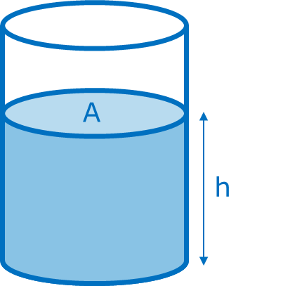
The volume of liquid to the level h metres is Ah
We know that density (ρ) = mass(m)/volume(V)
m = ρ × V = ρ × Ah
The weight of the liquid will be
W = mg = ρAhg
Pressure P = W/A = ρhAg/A
P = ρhg
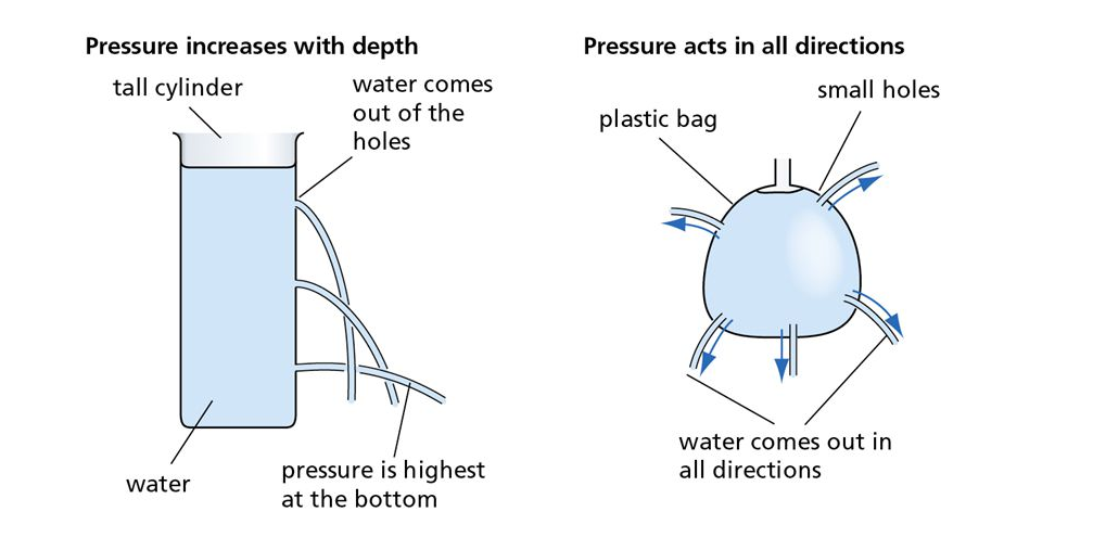
Characteristics of liquid pressure
- The pressure in a liquid increases as the depth of the liquid increases
- The pressure at the same depth (level) in different liquids varies proportionally with the density of the liquid.
- The pressure at any point on the same level within a liquid is the same
- Pressure at any point in the liquid at the same level acts equally in all directions
Pressure enables water to flow into various taps in a building from one tank placed at the rooftop.
Dams are constructed in a such a way that the base are built thicker than the top to withstand a larger pressure (because the pressure is larger at the bottom than at the top)
Example: A jar 0.6m deep is full of liquid of density 1200kgm-3. At what depth below the surface of the liquid is its pressure equal to 900Nm-2. (Take g=10ms-2)
P= ρhg, P = 900Nm-2, ρ = 1200kgm-3, h=?
h = P/ρg = 900/(1200×10)
h = 0.075m
Applications of Pressure and Pressure Devices
Pressure has a wide variety of applications. It finds its use in many devices. We may categorize them into
1) Liquid pressure devices e.g. hydraulic press, car braking system, Hare’s apparatus, syringe, siphon
2) Atmospheric and air pressure devices e.g. simple barometer, Fortin barometer, aneroid barometer, bicycle pump, syringe, lift pump, force pump
3) Gas pressure measuring devices as in manometer or Bordon’s guage
Hydraulic Press
It works on the principle that pressure is transmitted equally to all parts of a liquid at the same level. It consists of two cylinders joined by a connecting tube filled with a liquid. The bore of one cylinder is smaller than that of the other. A tight piston is fitted to the small bore and large bore of the cylinders.
A small force f acting on the small piston of cross-sectional area a transmits pressure p=f/a, via the liquid of the large piston in the wide cylinder of area A. A large force F on the area A produced
“Pressure”=f/a=F/A
F=A.f/a
The hydraulic press is used in the printing press where a large force produced presses ink against a paper.
Also used in the hydraulic jack to lift a heavy car or in the textile industry to compress bales of cotton or wool.
*
NEWTONS’S LAWS OF MOTIONS
We have studied the motion of objects alone in previous chapters without considering the forces producing them. This branch of physics that studies this is called kinematics.
In this chapter however, we shall study the effect of forces on bodies that are in motion: dynamics
Dynamics is that branch of physics that studies these effects.
Quite a number of scientists and physicists have contributed enormously to the study of dynamics e.g. Galilei Galileo, who initiated the study of dynamics, Isaac Newton (1642 – 1727) formulated the basic laws of motion that are still valid today.
The fundamental principles of motion are summed up in Newton’s three laws of motion.
Newton’s First law of motion
Every object will continue in its present state of rest or in uniform motion in a straight line unless it is acted upon by an external force.
The law brought in the concept of inertia and is sometimes referred to as the law of inertia. Inertia is the reluctance of a body to move when at rest and also the reluctance to stop moving when in motion.
It is important to realize that once a body is moving with uniform speed in a straight line, it needs no force to keep it in motion provided there are no opposing or external forces.
In general, however, it does not appear the law is obeyed from common experience in practical situations; a ball kicked come to rest after some time.
The law is actually not disobeyed. A body comes to rest when in uniform motion by external forces. E.g. The ball moving in a straight line will gradually come to rest by opposing forces from air resistance and friction (external forces). A body thrown up in the air will come down as a result of the pull of gravity (external force).
We observe that when a moving vehicle is suddenly brought to rest by the application of brakes, the passengers are suddenly jerked forward as they tend to continue in their straightline motion. Passengers in the front seat may collide with the windscreen causing serious injuries unless a backward force is applied. This is why it is advisable to use seat belts.
Newton’s second law of motion
The rate of change of momentum of a body is directly proportional to the applied force and takes place in the direction of the force.
Momentum
The momentum of a body is defined as the product of its mass and its velocity.
Momentum(M) = mass(m) × velocity(v)
M = mv
The unit of momentum is kgms-1
Momentum is an important property of a moving object. A bullet having a small mass 0.01kg, moving with a high velocity of 3000ms-1 AND a heavy ball of mass 30kg, moving at a small speed of 1ms-1 have the same momentum of 30kgms-1
More powerful brakes are required to stop a heavy lorry due to its large momentum than a car with a smaller momentum.
From the second law; force ∝ change in momentum/”time”
Suppose a force F acts on a body of mass m for a time t and causes it to change its velocity from u to v, then from the second law

This constant has been so defined that if a mass 1kg has an acceleration of 1ms-2, the force is 1N, so k=1 and
F = ma
This equation is recognized as one of the most important equations of physics and a fundamental equation in dynamics
NOTE that the force F must be the resultant force acting on the body.
Example: A resultant force of magnitude 15N acts on a body of mass 250g. Calculate the magnitude of the acceleration. [WASSCE’ 12]
m = 250g or 0.25kg, F = 15N, F = ma
a = F/m = 15/0.25 = 60 ms-2
Example: A car of mass 500kg, moving with a forward acceleration of 5ms-2 is acted upon by a constant resistive force of 1000N. Calculate the force exerted from the engine to maintain this forward acceleration.
Let Fe be the force exerted from the engine, the resultant force acting on the car, Fe – 1000
Fe – 1000 = 500 × 5
Fe = 2500 + 1000 = 3500N
Impulse of a force
Impulse is the product of a force on an object and the time t this force acts.
Impulse (I) = Ft
The unit of impulse is Ns
This force is usually a large one and the time interval very small. For example, a player applies a force of 200N for 0.1s to kick a ball, the impulse(I) on the ball
is I = 200 × 0.1 = 20Ns
Now from F = (mv-mu)/t
Ft = mv-mu
We see that the quantity Impulse is equal to the change in momentum
I = Ft (change in momentum)
Example: A body of mass 5kg moving with a speed of 30ms-1 is suddenly hit by another body moving in the same direction thereby changing the speed of the former body to 60ms-1. What is the impulse received by the first body?
Impulse (I) = change in momentum = mv-mu
m = 5kg, u = 30ms-1, v = 60ms-1
I = 5(60-30) = 150Ns
Force and weight
Any body of mass m falling under gravity has an acceleration a = g = 10 ms-2.
Thus, the force of gravity acting downwards on the body is F=mg. This force is called the weight of the body.
Hence W =mg
Example: a body of mass 5kg is to be given an acceleration of 20ms-2. Calculate the force required when the acceleration is upwards. [g=10ms-2]
This force must overcome the downward opposing force of gravity (weight of the body) and still give the body the required upward acceleration
F = mg + ma, m = 5kg, g = 10ms-2, a = 20ms-2
F = 5(10) + 5(20) = 50 + 100
F = 150N
Concept of weightlessness (a body in a lift)
Consider a man in a lift (a device used to move people up and down tall building. There are two forces acting on him; his weight W acting downwards and the reaction R of the floor of the lift on the man, acting upwards
Let us look at four scenario situations
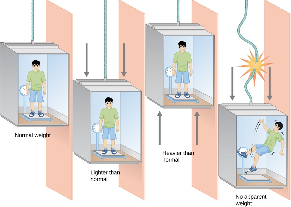
1) When the lift is stationary or moving with a constant velocity, it is not accelerating and a = 0
The weight of the body is equal to the reaction of the lift
W = R = mg
2) When the lift moves downwards with an acceleration a:
mg – R = ma
W = mg – ma
The man appears to weigh less under this condition
3) When the lift accelerates upwards with an acceleration a, the man is pulled upwards with an acceleration = a
R – mg = ma
W = R = mg + ma
The man appears to weigh more under this condition
4) When the lift descends with acceleration (as though the lift was dropped or the cable was cut)
a = g, then W = mg – ma becomes
W = mg – mg = 0
The man appears to have no weight. Under this condition, he is said to be weightless
Example: A man of mass 50kg ascends a building standing on a scale in a lift accelerating at 2ms-2. what would be the scale reading as he approaches his destination.
Weight of the body due to gravity = mg = 50 × 10 = 500N
W = R = mg + ma
= 50(10) + 50(2) = 600N
Newton’s third law
To every action, there is an equal and opposite reaction.
If we place a book on a table, the weight of the book, (action) acting downwards is equal to the reaction of the table on the book acting upwards.
Again, if a car A hits a stationary car B, the reaction force of B on A is equal to the action force of A on B. Thus both cars are damaged.
Effects of Newton’s second and third law
1) Recoil of a gun: when a bullet is shot out of a gun, the shooter experiences a backwards force of the gun (reaction) as a result of the forward propulsive force of the bullet (action)
If M is the mass of the gun, m is the mass of the bullet, v is the velocity of the bullet and V is the recoil velocity of the gun
MV = -mv
and V = -mv/M
The negative sign of the recoil velocity simply means that the it is opposite the direction of the bullet
2) Rocket propulsion and jet engines: their application is based on the fact that a large mass of very hot gasses produced from the combustion of fuel and air is issued out at high velocity from the nozzle behind the jet or rocket.
Examples
1) A bullet of mass 0.045kg is fired from a gun of 9kg, the bullet moving with an initial velocity of 200ms-1. Find the initial backward velocity of the gun.
2) A rocket expels gas at the rate of 0.4kgs-1. If the average force of the gas is 120N, calculate the velocity of the gas.
1) M = 9kg, V = ?, m = 0.045kg, v = 200ms-1
MV = mv, V = mv/M = (0.045×200)/9 = 1 ms-1
The negative sign was omitted. It has a backward velocity of 1 ms-1
2) Mass of gas expelled per second = 0.4kgs-1
Recall from second law that
F = momentum change per second=
mass of gas expelled per second × velocity
F = 0.4 × v
but F = 120N, ∴120 = 0.4 × v
v = 120/0.4 = 300ms-1
Conservation of momentum
When two bodies collide, there is a change in momentum of the individual bodies. However the total momentum does not change, it is conserved.
The principle of conservation of momentum states that when two or more bodies collide, the total momentum before collision is equal to the total momentum after collision.
It is assumed that the system of colliding bodies is a closed system i.e. no net external forces act on the system.
The principle of conservation of momentum is a consequence of Newton’s second and third law.
Consider two bodies of masses mA and mB moving towards each other with initial velocities uA and uB respectively
Let the acceleration of A be aA and B be aB
Then at collision and from Newton’s third law, the force of A is equal and opposite to the force on B

Example: A body C of mass 10kg moving with a velocity of 50ms-1 collides with another body D, moving in the opposite direction with a velocity of 20ms-1. If both bodies now move in the direction of C at a velocity of 10ms-1, calculate the mass of Q.

Before Collision
After Collision
since momentum is a vector quantity, we must take into consideration the directions of motion.
Let us take the direction of C to be positive, hence the direction of D will be negative
mC = 10kg, uC = 50ms-1, mD = ?, uD = -20ms-1, vC = vD = 10ms-1
Total momentum before collision = total momentum after collision
(10 × 50) + (mD × (- 20)) = (10 × 10) + (mD × 10)
500 – 20mD = 100+ 10mD
500-100 = 20mD + 10mD
400 = 30mD ⇒ mD = 400/30 = 13.3kg
Types of collision
Elastic collision
In elastic collision, both momentum and kinetic energy are conserved. If the kinetic energy is the same before and after collisions, it is referred to as a perfectly elastic collision.
If we consider again two bodies A and B of masses mA and mB moving with initial velocities uA and uB before collision and final velocities vA and vB after collision, and the collision is perfectly elastic, then from the principle of conservation of momentum and the conservation of kinetic energy, we can write
mAuA + mBuB = mAvA + mBvB and

Examples of nearly perfect elastic collision include collision of molecules, collision of billiard balls.
Also, if a ball bounces off the ground and returns to its original height, the collision is perfectly elastic
Inelastic collision
In this type of collision, the total momentum is conserved but the kinetic energy is not. The kinetic energy usually decreases and is converted or lost to heat, sound or elastic potential energy (deformed).
In elastic collision, the colliding bodies stick together and move with a common velocity after collision.
Thus vA = vB = v and
mAuA + mBuB = (mA + mB)v

Example: Two bodies P and Q are moving towards each other and they collide. P has a mass of 6kg and Q 3kg. The velocities of P and Q before collision were 3ms-1 and 2ms-1. If the collision is perfectly inelastic, find the velocity of the two bodies after collision. Find the total kinetic energy of the system before and after collision and hence deduce the loss in kinetic energy
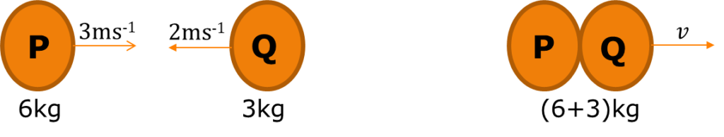
From conservation of momentum
(6 × 3) + (3 × (-2)) = (6 + 3)v
18-6 = 9v ⇒ v=12/9 = 1.33ms-1
Kinetic energy before collision
1/2 (6) (3)2 + 1/2 (3) (-2)2 = 27 + 6 = 33J
Kinetic energy after collision
1/2 (6 + 3) (1.33)2 = 8J
Loss in kinetic energy: 33 – 8 = 22J
HEAT & TEMPERATURE I
HEAT
Heat is a form of energy that produces a feeling of hotness.
When we place a pot of cold water on a heater, after a few minutes, the water feels hotter when we touch it. We say that heat has flowed from the heater to the cold water.
Uses of heat
- For cooking our food, warming our homes or cars, drying our clothes.
- Vehicles are able to move as a result of heat produced in the engine from the combustion of fuels.
- Industrially, extraction of metals from the ores, melting and shaping of metals, glass and plastics into different shapes is made possible through heat.
The above mentioned work activity that is done by heat confirms that heat is a form of energy, it is referred to as thermal energy.
Temperature
Temperature is the degree of hotness or coldness of a body.
Heat flow causes temperature change. Heat flows from a body at higher temperature to a body at lower temperature.
Thus, if a hot object is placed in close contact with a cold object, heat flows from the hot object to the cold object. As a result of this, the temperature of the hot object decreases and the that of the cold object increases.
Effects of heat
Whenever heat is applied to a body, various changes can occur:
- Change in temperature: addition of heat causes a rise in temperature, while the removal of heat causes the temperature of a body to fall.
- Change of state: addition of heat causes the transition of the state of a body e.g. from solid to liquid, liquid to gas etc.
- Expansion of the body: when heat is added to a body, the body expands. It contracts when heat is removed
- Change in chemical properties: heat supplied or removed brings about changes in the chemical properties of a substance.
- Change in physical properties: heat can cause changes in the electrical resistance, elasticity, density or even colour of a body
- Changes in pressure and volume: heat added to a fluid (liquid or gas) causes an increase in the pressure and volume of a gas.
- Thermionic emission occurs: this is the emission of electrons from the surface of a metal as a result of heat.
Differences between heat and tempearature
| Heat | Temperature |
|---|---|
| 1) Heat is a measure of the total internal energy of a body | Temperature is a measure of the hotness or coldness of a body |
| 2) Heat flows from a region of higher temperature to a region of lower temperature | Temperature does not flow |
| 3) Heat cannot be directly measured with any instrument. It can only be calculated | Temperature is measured by means of an instrument called a thermometer |
| 4) The unit of heat is Joule (J) | The S.I. unit of temperature is Kelvin (K) |
Measurement of temperature
Temperature is measured by an instrument called a thermometer.
Temperature measurement is very important as it provides for example an indication of good or poor health. The temperature of a human body in good health is 370C.
The various thermometers make use of a substance whose physical property varies in a known way with change in temperature. Such a substance is called a thermometric substance.
| Type of thermometer | Thermometric substance | Physical property of substance |
|---|---|---|
| 1) Liquid-in-glass thermometer | Mercury or alcohol | Change in volume of liquid with change in temperature |
| 2) Gas thermometer | Gas | Pressure of gas (at constant volume) or volume of gas (at constant pressure) changes with temperature |
| 3) Resistance thermometer | Resistance | Increase in resistance of wire with increase in temperature |
| 4) Thermometric thermometer | Two dissimilar metals | Change in current due to change in temperature difference between the 2 metals |
Fixed Points and Temperature Scales
Thermometers have two reference temperatures or fixed points and they are the upper fixed point and lower fixed point.
The upper fixed point is the temperature of steam in contact with water boiling at standard atmospheric pressure, 760mm of mercury.
The lower fixed point is the temperature of the melting point of pure ice at standard atmospheric pressure.
The difference in temperature between the two fixed points is called the fundamental interval and the calibration or division of this interval depends on the temperature scale used.
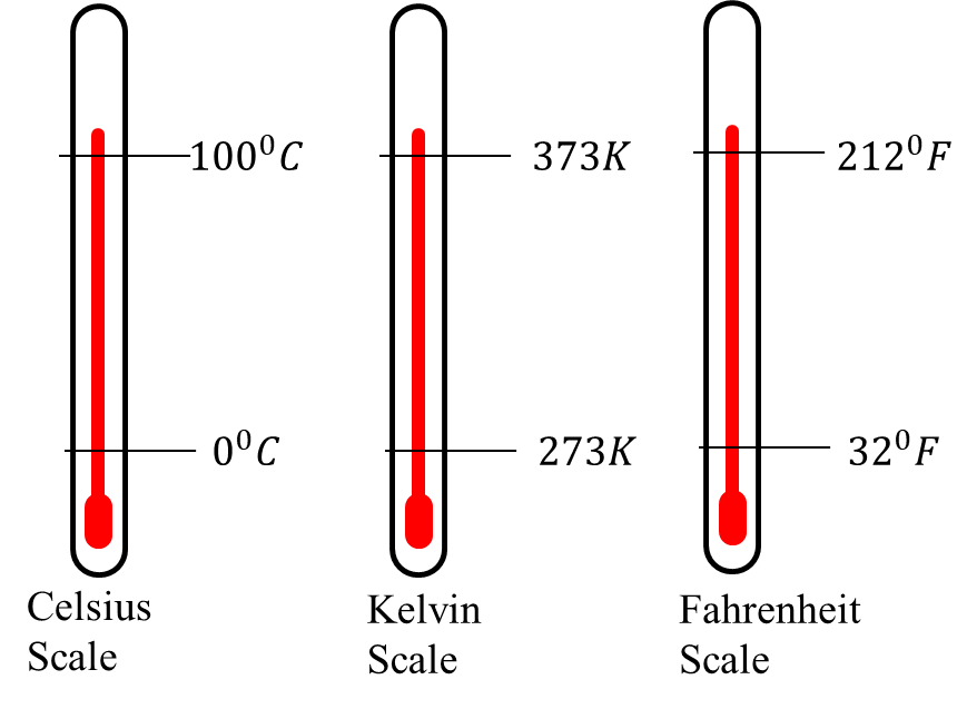
The three basic types of temperature scale used are
- The Celsius or centigrade scale (0C)
- The Kelvin scale (K)
- The Fahrenheit scale (0F)
The fundamental interval on a Celsius scale has 100 divisions and each division defines one degree. So the lower fixed point is taken to be 00C and the upper fixed point 1000C. The Celsius scale is used globally in scientific work.
The S.I. unit of temperature is the Kelvin (K) and its scale is called the absolute or thermodynamic or simply Kelvin scale.
The fundamental interval also has 100 divisions but a lower fixed point of 273K and an upper fixed point of 373K. Each division corresponds to 1K. There exist a lowest possible temperature on this scale referred to as absolute zero below which nothing can be cooled and is equal to 0K (-2730C).
A temperature change of 10C is equal to a temperature change of 1K. Kelvin scale has no negative temperatures and it is measured in units called Kelvin (K) and not in degrees.
Let also Tl and Tu be the lower and upper fixed point temperature of the unknown temperature scale and let θl and θu represent the lower and upper fixed point temperature on the given scale. Then by interpolation

We only need to remember the fixed point of each scale
Formula method
To convert a temperature from Celsius scale Tc to Kelvin scale Tk.
Tk = Tc + 273
And by simple change of subject, a temperature in Kelvin can be converted to Celsius Tc = Tk + 273
To convert a temperature from Celsius scale Tc to Fahrenheit scale Tf
Tf = 9/5 Tc + 32
Tc = 5/9(Tf – 32)
Example: Convert 350C to a) Kelvin scale b) Fahrenheit scale
General method
a) Given scale is Celsius θ = 350C, θl = 00C, θu = 1000C
Unknown temperature scale is Kelvin Tx = ?, Tl = 273K, Tu = 373K

Tx – 273 = 35 ⇒ Tx = 35 + 273 = 308K
b) θ = 350C, θl = 00C, θu = 1000C, Tx = ?, Tl = 320F, Tu = 2120F

Formula method
a) T_K=T_C+273, T_C=35^0C
T_K=35+273=308K
b) T_F=9/5 T_C+32, T_F=9/5 “×” 35+32
T_F=63+32=95^0 “F”
Although the formula method may look straight forward and easy, however understanding the general method helps to easily understand calculations in other types of thermometers
Types of Thermometer
1) liquid-in-glass thermometer
Common liquids used in this type of thermometer are mercury and alcohol, although mercury is more widely used. The thermometer measures temperature by measuring the change in volume of a fixed mass of liquid due to change in temperature. *
A good liquid-in-glass thermometer should have
a)a bulb made of thin glass to enable it quickly assume the temperature of its surrounding or substance to be measured
b)a uniform bore and a narrow capillary tube which makes it possible for a small change in temperature to cause a significant change in length of the mercury column
c)a liquid with high thermal expansivity, high boiling and low melting point, expand or contract uniformly with temperature and should be opaque.
Comparing mercury and alcohol-in-glass thermometers
| Advantages of mercury | Disadvantages of alcohol |
| 1) Mercury boils at 3570C and can be used to measure higher temperatures | Alcohol boils at 780C and cannot be used to measure high temperatures |
| 2) Has a higher conductivity and thus responds more rapidly to temperature changes | A relatively poor conductor, expands slowly and responds slowly to temperature changes |
| 3) It is opaque and can be easily seen | Alcohol has to be coloured before it can be seen |
| 4) Does not wet glass, so it responds to falling temperature accurately | Wets glass and can lead to inaccurate readings |
| 5) Mercury is not easily vapourized | Vapourizes easily even at low temperatures |
| Advantages of alcohol | Disadvantages of mercury |
| 1) Freezes at -1150C and can be used to measure lower temperatures than mercury | Freezes at -390C, cannot measure low temperatures |
| 2) Expands about six times as much as mercury for the same temperature rise | Low expansivity |
Examples of liquid-in-glass thermometers
1)Clinical thermometer: This is a form of mercury-in-glass thermometer used to measure the temperature of the human body. It has a short range (350C to 430C). The temperature of a normal healthy person is 370C but may rise to 410C in conditions of high fever.
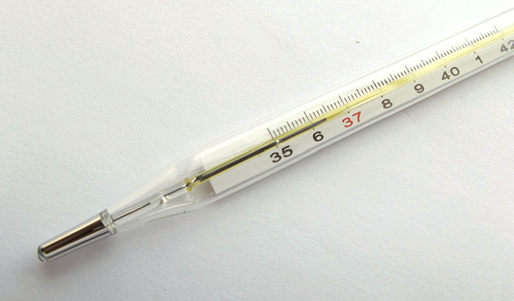
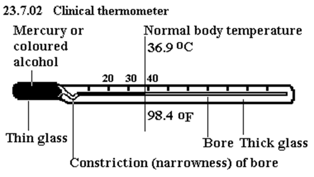
When placed in contact with the human body, the mercury expands and pushes past the kink or constriction. When the thermometer is taken away from the body, the thread of mercury remains in position as it cannot flow back through the constriction. The temperature of the body can be read. To use the thermometer again, it is jerked vigorously to force the mercury back to the bulb through the constriction.
2) Maximum and minimum thermometer: this type of thermometer records the maximum and minimum temperature over a period. It was invented by James Six in 1782 and is also referred to as Six’s thermometer. It is used in metrological stations and weather studies to record both the maximum and minimum temperatures for the day
*
It consists of a U-shaped capillary tube connected to two large bulbs A and B. both bulbs contain alcohol which are separated by a column of mercury in the bend of the tube. A is completely filled with alcohol and B contains a little air. Two steel indices X and Y are kept in position by light springs above the mercury on both sides of the tube. The thermometer is calibrated on both limbs of the U-tube.
An increase in temperature causes the alcohol to expand and since it expands more than mercury, it pushes the mercury column from A round the thermometer. The mercury column at Y pushes upwards and the reading of the lower end of the steel index Y gives the maximum temperature
Decrease in temperature causes the alcohol to contract. Mercury moves up the minimum area pushing the index X upwards.
The lower end reading of X gives the minimum temperature.
A magnet brought in contact with the mercury column is used to reset each index and the thermometer is ready for use again.
Finding the lower and upper fixed point of a thermometer
The upper fixed point of an unmarked thermometer can be found using a hysometer: a double-walled calorimeter construction as shown
*
The thermometer is placed in the steam in the inner chamber above the boiling water. A manometer is used to measure the pressure of the steam to ensure it is 760mmHg.
This is achieved when the heights of the mercury column are the same.
When the mercury level in the thermometer is steady, a mark is made on the glass at this level.
This is the upper fixed point.
The lower fixed point is determined by placing the thermometer upright in pure melting ice. When the level of the mercury is constant, a mark is made at that level on the glass.
It represents the lower fixed point. The distance between these two fixed points determined can now be divided into 100 or 180 divisions depending on the scale to be used.
Gas thermometer
For very accurate measurements, mercury-in-glass thermometer cannot be used. Also the temperature range from such thermometers (-390C to 3570C) is relatively small.
Gas thermometer cover these lapses in that they are used for accurate temperature measurements and has a wide range of about -2700C to 15000C. The principle of gas thermometer is based on the fact that at constant volume, the pressure of a gas increases linearly (directly proportional) with temperature.
A simple form of constant volume gas thermometer consist of a large bulb containing air (or a gas such as hydrogen) and connected by a narrow (capillary) tube to a manometer. When the gas is heated in the bulb to a certain temperature, the gas expands and pushes the mercury down in tube B and up in tube A. The right side BD of the manometer is moved up or down to bring the mercury level on the other side to a fixed mass C. The volume of the gas is kept constant in this way. The pressure of the gas is then read from the manometer.
If the distance between the mercury levels in C and B is h, then the gas pressure when the mercury in B is above C is given by P=H+h where H is the atmospheric pressure
However, when the mercury in B is lower than that in C, the gas pressure becomes P=H-h
The thermometer is calibrated by first measuring the gas pressure at 00C when the bulb is placed in melting ice, this is P_0 and then at 1000C when the bulb is placed over steam P_100.
A linear graph of pressure versus temperature is plotted using these two measured points
*
Advantages
It is very accurate and highly sensitive. It also has a wide range (-2700C to 15000C) and is used in the calibration of other thermometers
Disadvantages
1)It is large and cumbersome and therefore not suitable for measuring temperature of small volume of liquids.
2)The knowledge of the pressure of the gas at the fixed points must be known every time the instrument is to be used.
Example
*
Resistance thermometers
The principle of this type of the thermometer is based on the fact that the electrical resistance of a metallic conductor is proportional to its temperature. The most common type of this thermometer is the platinum resistance thermometer.
*
The resistance R_x at a particular temperature θ is measured by employing a Wheatstone bridge. Measurement of the resistance R_0 at 00C (ice point), and R_100 at 1000C (steam point) are taken. In most cases, the resistance scale is calibrated to read the temperature in degrees.
From the general method of temperature conversion, we can say that
(R_x-R_0)/(R_100-R_0 )=(θ-0)/(100-0)
θ/100=(R_x-R_0)/(R_100-R_0 )
Resistance thermometers can provide accurate measurement and also, they have a wide range. However, it is not suitable for measuring rapid changes in temperature
*
Thermoelectric thermometers
This thermometer is based on the working principle of the thermocouple. A thermocouple consists of two dissimilar metals e.g. copper/constantan or copper/iron joined together at the ends. One end is placed in hot water and heated (hot junction) while the other end is kept constant by immersing it in melting ice (cold junction) and a galvanometer (a sensitive current measuring instrument) is connected in series with the hot and cold junctions.
The current measured depends on the temperature difference between the hot and cold junctions.
The galvanometer is usually calibrated in such a way as to read the temperature of the hot junction directly
Advantages
1)It is particularly used for measuring rapidly changing temperature
2)Its small size allows it to measure temperature even at a point
3)Employed in industries to measure high temperatures of up to 11000C
*
THERMAL EXPANSIVITY
THERMAL EXPANSION OF SOLIDS AND LIQUIDS
Expansion of solids
Most solids expand when heated and contract when cooled. The rate of expansion and contraction differs for different solids, for example, brass expands more than iron for same temperature rise
Consequences and effects of expansion
1)Railway tracks and bridges
Railway sections have gaps between them to make allowance for expansion due to temperature rise, otherwise the rails would buckle during hot days and trains would be derailed.
Steel bridges fixed at both ends would expand during hot weather and the large force that would be exerted against its fixtures may cause the bridge to fracture. To prevent it, one end of the bridge is fixed and the other end rests on rollers in an expansion gap so that the metal is free to expand and contract during seasons of summer or winter

2)Cracking of glass
A thick glass bottle or drinking-glass will crack if hot water is poured into it. Since glass is a poor conductor of heat, the outer, colder glass expands much less than the hot glass on the inside. To prevent the cracking, only a small quantity of water at a time should be poured in to allow for time for even expansion of the glass inside and outside
*
3)Sagging of telephone and overhead wires
The metals used for making these wires expand and sag during hot weather. They could snap if they are taut to the poles due to expansion. They also contract during cold weather. To avoid their snapping, the wires are usually given a certain amount of sag to give room for expansion and contraction.
Applications of expansion
1)Rivets
The construction of large boilers and building of ships make use of steel plates riveted together using very hot rivets. The hot rivets is pushed through overlapping plates and hammered tight. On cooling, the rivets contract and holds the plates even more tightly together.
It provides a good seal against steam in boilers and against the sea for ships plates.
*
2.Bimetallic strips
One of the most important application of solid expansion is the bimetallic used in many different appliances. It is made by placing two strips of different metals (e.g. brass and iron) side by side and welding them along their entire length.
If the bimetallic strip is heated, it curves as shown
*
with the brass being on the outside and iron on the inside. This shows that brass expands more than iron for the same temperature rise. The strip straightens at room temperature. If it were cooled below room temperature, the brass would contract more than iron
The bimetallic strip has several applications
a) Bimetallic strip thermometer: this thermometer consists of a spiral strip made from brass on the outside and invar (a steel-nickel alloy which expands very little) on the inside. One end of the strip is fixed and the other end is attached to a pointer
Uneven expansion of the metals due to temperature rise causes the strip to curve in a clockwise direction making the pointer move over a calibrated scale to measure the temperature
b) Thermostat
A thermostat is a device used for controlling the temperature . A thermostat is used in electric iron and gas oven. A thermostat is made from a bimetallic strip.
When the current is switched on in an electric iron and the thermostat knob is set to the desired temperature, the current flows and produces heat.
When the desired temperature is attained, the strip (thermostat) is now curved and separates from the contact point, thereby breaking the contact and switching off the current. As the strip cools down and straightens up, it makes contact thus switching on the current again. This make-and-break mechanism controls the temperature of the electric iron.
c) Electric fire alarm
When there is a fire outbreak in a building, the resulting heat causes the strip to bend and make contact with the bell causing it to ring out a fire alarm.
Linear expansivity of a solid
The linear exapnsivity (α) of a solid is defined as the increase in length per unit length per degree rise in temperature.
Mathematically
α=(l_2-l_1)/(l_1 (θ_2-θ_1 ) )=(increase in length)/(original length×temperature rise)
The unit of linear expansivity α is 0C^(-1) (per degree Celsius) or〖 K〗^(-1) (per Kelvin)
Where l_1=initial length at temperature θ_1, l_2=final length at temperature θ_2
α is also called coefficient of linear expansion.
From the above equation, αl_1 (θ_2-θ_1 )=l_2-l_1
Let ∆θ be temperature rise θ_2-θ_1 and ∆l be increase in length l_2-l_1
∆l=αl_1 ∆θ
When we say the linear expansivity of iron is 12×10^(-6) K^(-1), we mean that a unit length of iron increases by 12×10^(-6) unit when it is heated through 1K (or 10C) temperature rise.
NOTE that a unit change in the Kelvin scale corresponds to a unit change in the Celsius scale.
The values of linear expansivity (α) differs from solid to solid. Metals have the highest values of α
| Solid substance | Linear expansivity 〖(“in” K〗^(-1)) |
| Platinum | 9×10^(-6) |
| Iron | 12×10^(-6) |
| Copper | 17×10^(-6) |
| Brass | 18×10^(-6) |
| Aluminium | 23×10^(-6) |
| Lead | 29×10^(-6) |
| Zinc | 30×10^(-6) |
| Invar | 1×10^(-6) |
| Glass | 8.5×10^(-6) |
| Silica | 0.4×10^(-6) |
Example: A copper rod whose length is 10m at 300C is heated to 900C. Find its increase in length and its new length. [ Linear expansivity of copper = 1.7×10^(-5) K^(-1)]
α”=” 1.7″×” 10^(-5) K^(-1), l_1 “=” 10m, θ_1 “=” 300C, θ_2 “=” 900C, l_2=? α=(increase in length)/(original length×temperature rise)
1.7×10^(-5)=∆l/(10×(90-30) )
∆l=1.7×10^(-5)×10×60=0.0102″m”
Increase in length = 0.0102m
New length l_2= l_1+increase in length=10+0.0102
“new length”=10.0102″m”
Measuring the linear expansivity of a metal
The expansion of a solid when heated is usually so small that special apparatus is required to measure it accurately.
Area and volume expansivity
Expansion occurs in all directions when solids are heated. That is in length, breadth and in height. Thus, there is an increase in area and also volume of the solid
The area expansivity (β) is the increase in area per unit area per degree rise in temperature
β=(A_2-A_1)/(A_1 (θ_2-θ_1))
β=(A_2-A_1)/(A_1 ∆θ)⇒A_2-A_1=βA_1 ∆θ
A_2=A_1+βA_1 ∆θ=A_1 (1+β∆θ)
A_1 is initial area at θ_1, A_2 is final area at θ_2
The cubic or volume expansivity (γ) is the increase in volume per unit volume per degree rise in temperature
γ=(V_2-V_1)/(V_1 (θ_2-θ_1 ) )
Similarly V_2=V_1 (1+γ∆θ)
V_1 is initial volume at temperature θ_1, V_2 is final volume at θ_2
Let us now show the relationship between linear expansivity α, area expansivity β and cubic expansivity γ
Consider a rectangular sheet of metal of length l_1 and breadth b_1. Let the length now be l_2 and breadth b_2 after it has been heated through a temperature rise ∆θ
Initial area of metal sheet =A_1=l_1 b_1
Final area A_2=l_2 b_2
From area expansivity, A_2=A_1 (1+β∆θ) and from linear expansivity, l_2=l_1 (1+α∆θ), similarly, b_2=b_1 (1+α∆θ)
A_2=A_1 (1+β∆θ)=l_2 b_2
A_1 (1+β∆θ)=l_1 (1+α∆θ).b_1 (1+α∆θ)
A_1 (1+β∆θ)=l_1 b_1 (1+2α∆θ+α^2 (∆θ)^2)
Since α is a small quantity (in the range of 10^(-5)), α^2 will be extremely small and can be approximated to zero.
∴A_1 (1+β∆θ)=l_1 b_1 (1+2α∆θ)
By comparing, β=2α
Similarly it can be shown that the cubic expansivity γ and the linear expansivity α are related by the relation γ=3α
Expansion in liquid
All liquids expand when heated. Their expansion is characterized by a change in volume when there is a change in temperature. Generally, liquids expands about ten times more than solids do for the same temperature rise.
*
The expansion in liquids is made complicated by the expansion of their containers. It is therefore necessary to distinguish between the real and apparent cubic expansivity of a liquid.
The real (absolute) cubic expansivity γ_r of a liquid is the increase in volume per unit volume per degree rise in temperature.
The apparent cubic expansivity γ_a of a liquid is the increase in length per unit length per degree rise in temperature when the liquid is placed in an expansible vessel.
Now the apparent cubic expansivity takes into account the cubic expansivity of the material of the containing vessel (γ).
The real expansivity is always more than the apparent expansivity. We can write
γ_r=γ_a+γ
The difference between the real and the apparent cubic expansivtiy is the cubic expansivity of the vessel.
Anomalous behaviour of water
Most liquids expand when heated and contract when cooled. Water however and few other liquids do not expand continously with increase in temperature.
Ice (solid water) expands slightly when heated from -50C to 00C. At 00C it forms water and when it is further heated to 40C, it contracts! (rather than expand). This is abnormal and exceptional, but from 40C to 1000C, it expands behaving like most other liquids. Thus water has its least volume at 40C and hence maximum density at 40C.

This anomalous behaviour is beneficial in nature. Ponds, lakes and rivers freeze from the top surface rather than from the bottom. So ice at 00C is formed at the surface of the pond, while water at 40C is still available at the bottom so marine and plant life can survive.
HEAT & TEMPERATURE II
HEAT CAPACITY
Experimental studies have shown that the rise in temperature of a body is related to
a) its mass,
b) the quantity of heat it receives and
c) the material the body is made up of
This relation is expressed mathematically as
Q = mc∆θ
Where Q is the quantity of heat received or supplied to the body, m is the mass of the body, ∆θ is the change in temperature. c is a constant called specific heat capacity which depends on the material of the body.
The unit of Q is Joule (J), m is kg, ∆θ is Kelvin, the unit of c then becomes Jkg-1K-1. we can define the specific heat capacity c as the quantity of heat required to raise the temperature of a unit mass of substance through 1K (or 10C) rise in temperature.
The specific heat capacity of water is 4200Jkg-1K-1. this means that we require 4200J of heat to raise the temperature of 1kg of water by 1K.
The heat capacity C is the amount of heat required to raise the temperature of a body by 10C or 1K.
Q = C∆θ C has units JK-1
Specific heat capacity of some substances
| Substance | Specific heat capacity (Jkg-1K-1) |
| Brass | 380 |
| Copper | 400 |
| Zinc | 380 |
| Iron | 450 |
| Aluminium | 900 |
| Lead | 130 |
| Mercury | 140 |
| Ice | 2100 |
| Water | 4200 |
| Alcohol | 2500 |
| Paraffin (kerosene) | 2130 |
Example: What quantity of heat is needed to raise the temperature of 600g of iron from 200C to 900C? (specific heat capacity of iron =460Jkg-1K-1)
Q = ? m = 600g = 0.6kg, c = 460Jkg-1K-1, ∆θ = 90-20 = 700C (or 70K)
Q = mc∆θ = 0.6 × 460 × 70
= 19320J or 19.32kJ
Measurement of specific heat capacity of solid
The specific heat capacity of a solid can be measured using two methods
1) Method of mixtures
2) Electrical method
Method of mixtures
This is a more common method. It involves the transfer of heat or heat exchange between a hot metal and water in a vessel called a calorimeter. The calorimeter is usually made of copper or aluminium which are good conductors.
Loss of heat to the surrounding which is to be avoided is usually possible in this experiment. Heat may be lost through the processes of conduction, convection, radiation or evaporation. Heat loss is prevented by conduction when the calorimeter is surrounded by cotton wool (a poor conductor). This is referred to as lagging.
Losses due to convection and evaporation are prevented by providing an insulating lid as a cover fitted with two holes for thermometer and stirrer. When the calorimeter is polished on the inside and outside, heat loss to radiation is prevented.
The solid whose specific heat capacity c is to be measured, usually in the form of a metal block is weighed (mb). It is then tied to a string and left for some minutes placed in a beaker of boiling water. The temperature of the boiling water is recorded which is the temperature of the metal block, θb. The weight of the calorimeter is measured empty mc and measured when it is about two-thirds full with water (mcw). The temperature of the water is also recorded (θcw)
The hot solid is quickly transferred to the water in the calorimeter. It is gently stirred with a stirrer to ensure uniform distribution. The final steady temperature of the mixture is taken (θm).
At this point,
heat loss by hot metal = heat gained by water and calorimeter
mb c (θb – θm) = (mcw – mc) cw (θm – θcw) + mc cc (θm – θcw)
The hot metal experiences a decrease in temperature θb – θm while the water and the calorimeter experience an increase in temperature θm – θcw

This formula should not be memorized, but rather the heat exchange process should be understood.
The following precautions should be taken
1) The calorimeter should be well lagged to prevent heat losses to the surroundings
2) The hot metal must be transferred quickly to the water in the calorimeter and the mixtures gently stirred thoroughly.
Electrical method
The metal block of known mass mb is fitted with two holes for a heater and thermometer. The block is thermally insulated from its surroundings by placing it in a lagged jacket. The initial temperature of the block is noted θi. The heater is switched on and the current I is allowed to flow for a time t when the temperature rise on the thermometer is at least 150C. The heater is then switched off. The final temperature of the metal block is recorded θf.
Using again the principle of conservation of heat energy,
Energy given by heater = heat gained by metal
IVt = mb c (θf – θi)

V is the potential difference across the heater, c is the unknown specific heat capacity of the metal block.
The power rating P ( = IV) may also be known of the heater and the specific heat capacity of the metal becomes c = Pt/mb(θf – θi)
2) A certain metal of mass 1.5kg at initial temperature 230C, absorbed heat from an electric heater of rating 75W for 4 minutes. If the final temperature of the metal was 480C, calculate the specific heat capacity of the metal and thus the heat capacity
m = 1.5kg, θi = 230C, θf = 480C, P = 75W, t = 4 × 60 = 240sec.
Heat supplied by heater = heat absorbed by metal
Pt = mc(θf – θi)
75 × 240 = 1.5 × c × (48 – 23)
18000 = 37.5c
c = 18000/37.5 = 480 Jkg-1K-1
Heat capacity C = Q/∆θ = 18000/(48-23)
C = 720 J1K-1
Latent Heat
When heat is supplied to a solid, the temperature of the solid rises steadily until a point is reached when the solid begins to melt and become a liquid. Further heat will change the liquid to gas. During this transition phase i.e. from solid to liquid or from liquid to gas, the temperature of the substance remains constant even though heat is being supplied to it. This heat which is not visible (as there is no temperature rise) is termed latent heat (it was known previously as ‘hidden’ heat)
Molecular explanation of latent heat
From kinetic theory, we know that the molecules of a solid are held together by strong forces of attraction. So, the latent heat is the energy needed to break these forces that hold the molecules of a solid in regular pattern. The molecules then move about more freely as they are now in liquid state.
Similarly, the latent heat to change a substance from liquid form to vapour form is the amount of energy to overcome the not so strong forces of attraction between the molecules of a liquid.
The molecules then become independent of each other and are now in gaseous form. The latent heat energy needed in this case (from liquid to gas) is much greater than from solid to liquid.
Latent Heat of Fusion
Let us first consider the change of state from solid to liquid.
The specific latent heat of fusion is the quantity of heat required to change a unit mass of substance from solid to liquid without change of temperature.
Specific latent heat of fusion is usually represented as l_f and has units of Jkg-1
Q = mlf
Where Q is the quantity if heat, m is mass.
The specific latent heat of fusion of ice is 336000Jkg-1. this means we require 336000J of heat to change 1kg of ice at 00C to water at 00C.
Example: How much heat is required to melt completely 5kg of ice at 00C (specific latent heat of fusion of ice = 336kJkg-1)
Q = mlf, Q = ? m = 5kg, lf = 336kJkg-1 or 336000Jkg-1
Q = 5 × 336000
Q = 1680000J or 1.68MJ
Latent Heat of Vapourization
The specific latent heat of vapourization is the quantity of heat required to change a unit mass of substance from liquid to gas without change in temperature
Q = mlv
Where lv is the latent heat of vapourization, Q is quantity of heat and m is the mass
Evaporation and Boiling
We notice that pools of water left on the road after rainfall soon disappear. The water has gradually turned from liquid to gas through the process of evaporation.
Evaporation is a process whereby a liquid turns spontaneously into vapour below its boiling point.
Evaporation takes place at all temperatures from the surface of a liquid. Some liquids evaporate easily; others do not. Liquids such as methylated spirit, petrol and ether which evaporate very easily have low boiling point and they are called volatile liquids
Various factors affect the rate of evaporation:
- Temperature of the liquid: the rate of evaporation increases with increasing temperature. We see this when we spread wet clothes on a line. They dry quicker during the day when the sun is out and the temperature is higher than at night.
- Area of liquid surface exposed: the greater the surface area, the higher the rate of evaporation. A wet cloth or sheet spread out dries faster than when it is folded
- Pressure: the rate of evaporation decreases as pressure increases.
- Nature of liquid: liquids with low boiling points evaporate faster than liquids with high boiling point. Ether with boiling point 350C will evaporate faster than mercury with boiling point 3570C
- Wind and dryness of air: the more windy the atmosphere, the faster the rate of evaporation. Also the dryness of air causes faster evaporation. We notice this when we bring wet clothes around the air of a working fan. The clothes dry faster than placed in still air. The draft or wind blows away the water vapour around the cloth causing more evaporation to take place.
Molecular explanations of evaporation
According to kinetic theory, a liquid consists of molecules in constant motion. The molecules have different velocities and move in different directions.
Near the surface of the liquid, some molecules with high velocities (and hence high kinetic energy) in an upward direction break through the surface.
The presence of draft of air or wind sweeps away the escaped molecules of vapour above the liquid surface making way for fresh molecules to escape. The average kinetic energy of the remaining molecules in the liquid is reduced and the temperature is thus lowered.
Thus evaporation brings about cooling of a liquid
Effects and Applications of Cooling Effect of Evaporation
Effects
If a few drops of methylated spirit or ether is dropped on our skin, it feels cold as the liquid evaporates. The latent heat needed to change the liquid to vapour is absorbed from the skin.
Water stored in earthen or clay pots is cooler than that stored in glass bottles. Evaporation takes place through the pores of the pot causing the water to cool.
In the human body, sweat evaporates from the surface of the skin and causes the body to cool.
Doctors try to reduce the felt by a patient during an injection process by first dabbing the area where the injection is to be applied with methylated spirit of ether to cooling it and thereby numbing that part.
Application
The refrigerator
The working principle of the refrigerator makes use of the cooling effect of evaporation
A volatile liquid called a refrigerant is put into the pipes surrounding the chamber where food is stored. Some common refrigerants include liquid ammonia or Freon (ethyl chloride).
As the liquid evaporates, it absorbs latent heat of vapourization from the surroundings inside the refrigerator thereby cooling the inside and its contents. The vapour formed is compressed into a pump into a condenser outside the refrigerator. The compressed vapour condenses and gives out latent heat and this is lost to the air by using metal cooling fins. The condensed vapour (now the liquid refrigerant) is forced into the pipes where it again evaporates. This continous process keeps the refrigerator chamber cold
Boiling
When liquid in a container is heated, its temperature rises and the liquid evaporates due to temperature increase. As the heating is continued, bubbles of vapour appear in the liquid which rise to the surface. At this point, the liquid is said to be boiling.
The temperature of the liquid remains constant during this period and is the boiling point of the liquid
Differences between evaporation and boiling
| Evaporation | Boiling |
| 1) It is the change from liquid to vapour at temperatures below the boiling point | It is the change from liquid to vapour at the boiling point temperature. |
| 2) It takes place at all temperatures | It takes place at a particular temperature (boiling point) for a given pressure. |
| 3) Occurs only at the surface of the liquid | Occurs throughout the liquid. |
| 4) Temperature is not steady during evaporation | Temperature is steady during boiling. |
Effects of Pressure and Impurities on Boiling and Freezing Points.
1) Increase in pressure on the surface of a liquid increases the boiling point of the liquid.
The converse is also true; a decrease in pressure lowers the boiling point of the liquid
The pressure cooker makes use of this fact in its application.
The pressure cooker is a strong cooking pot with a tightly fitted lid.
The guage controls the flow of steam. The pressure of the trapped gas increases the boiling point of water inside to about 1200C. Food is cooked faster as a higher cooking temperature is achieved.
2) Increase in pressure lowers the freezing point of a liquid (or melting point of a solid). An ice block subjected to high pressure will melt. But when this pressure is removed, the ice refreezes. This process is known as regelation.
3) At high altitudes, the pressure of the air is much lower than at ground levels so aircrafts flying at these altitudes need to be pressurized to keep people in the cabin area at their normal pressure (105Pa). If this wasn’t done, the reduced pressure can cause the blood to tend to boil leading to disastrous effects on the human body.
Astronauts must also wear space suits in space to keep them at the right pressure and to provide oxygen to breathe.
The presence of impurities or dissolved substances in a liquid increases the boiling point of the liquid but reduces the freezing point. If water and common salt are mixed, the mixture will boil at a temperature higher than 1000C and freeze at a temperature lower than 00C. Salts are poured on ice formed on road during winter to lower the freezing point. By this, melting of the ice takes place.
Saturated and Unsaturated Vapours
When a liquid evaporates in a closed container, the molecules of the vapour above the surface of a liquid exerts a pressure like those in any other gas. This pressure is called vapour pressure of the liquid.
When the enclosed space above a liquid contains as much vapour molecules such that it can no longer hold any more molecules, the vapour is said to be saturated and it exerts a pressure known as saturated vapour pressure (S.V.P.)
However, if the enclosed space can still contain more molecules then the vapour pressure (at that temperature) is unsaturated.
A saturated vapour is a vapour that is in contact with its liquid in a confined space.
A ‘dynamic equilibrum’ is reached when the number of molecules escaping from the liquid at a given time is equal to the number of molecules entering the liquid at the same time. Saturated vapour pressure increases with temperature.
Boilers used in industries and factories may burst when the saturated vapour pressure (as a result of high temperature) is too large.
Saturated Vapour Pressure and Boiling
The saturation vapour pressure of a liquid at its boiling point is equal to the atmospheric pressure. We may define boiling point of a liquid as follows; the boiling point of a liquid is that temperature at which the saturated vapour pressure is equal to the atmospheric pressure.
Water vapour in the atmosphere
Evaporation always takes place from rivers, lakes and oceans and so there is always some water vapour present in the atmosphere. The amount of this water vapour depends on the temperature and climatic conditions of that place. The amount of water vapour present in the atmosphere is termed as its humidity. Thus the air is very humid if there is a high percentage of water vapour in the atmosphere.
Very high humidities or very low ones are not suitable as it makes the body fell uncomfortable.
WAVES
Definition: A wave is a disturbance which travels through a medium from one point to another carrying energy along with it without causing any permanent displacement of the medium.
The study of waves is of great importance. We are able to see and hear people by means of light and sound waves. Energy can be transferred from a source through a medium with the help of waves and without the actual movement of the medium.
However, not all waves require a material medium to carry them. Light waves, radiant heat, radio waves etc do not need any material medium for propagation.
Classification of waves
There are two major classes to waves: electromagnetic and mechanical waves.
Mechanical waves are those waves that require a material medium for their propagation. Examples of such waves are water waves, sound waves, waves on a string or rope.
Electromagnetic waves on the other hand are those waves that do not require a material medium for propagation e.g. light waves, radio waves, X-rays etc.
Transverse and longitudinal waves
We can categorize waves based on the direction of source vibration with respect to the direction of travel of the wave.
A transverse wave is a wave which travels perpendicularly to the direction of the vibration of the source. E.g. water waves, * waves generated by plucking a string, * light waves
A longitudinal wave is one which travels in a direction parallel to the vibration of the source e.g. sound waves *
Production of mechanical waves
Water waves and ripple tank
Waves on a slinky spring
General representation of a wave
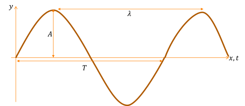
A wave can be represented in a graphical form.
y represents the direction of vibration of particles, while x represents the direction of travel of the wave. t is the time taken for the wave to travel
A cycle/oscillation/vibration is a complete to-and-fro movement of a particle of the wave.
A crest is the highest point on a wave.
A trough is the lowest point on a wave.
Terms used to describe a wave
1)Amplitude (A): This is the maximum displacement of the particles of the wave from their equilibrium (or rest) position. It is measured in metres.
2)Period (T): It is the time required for the wave to travel one complete cycle or oscillation. It is measured in seconds.
3)Frequency (f): It is the number of complete cycles or oscillation that the wave makes per second. The unit of frequency is Hertz
4)Wavelength (λ): This is the distance between two successive crests or two successive troughs. It is also the distance covered by the wave in one complete cycle. It is represented by λ (lamda) and is measured in metres.
5)Wavespeed (v): It is the distance the wave travels per unit time. Measured in ms^(-1) (metres per second) v=fλ
6)Phase: Two particles on a wave are said to be in phase if they are at the same vertical distances from their rest position and are moving in the same direction. e and g are in phase, f and h are in phase but e and f are out of phase
*
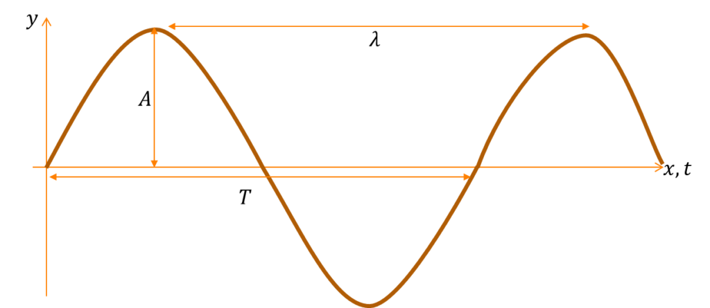
Relationship between T, f, λ and v
From the definition of T and f; in T seconds, 1 cycle is performed. In 1 second, 1/T cycles is performed
f=1/T “or” T=1/f
From the definition of wavespeed,
v=fλ
v=”distance travelled by wave” /”time taken”
Example: A wave travels at 300ms-1 with a frequency of 20Hz. Calculate the period and wavelength of the wave.
v=300ms^(-1), f=20Hz
T=1/f=1/20=0.05s
v=fλ⇒300=20×λ
λ=300/20=15m
Example: From the displacement-time graph of a wave shown
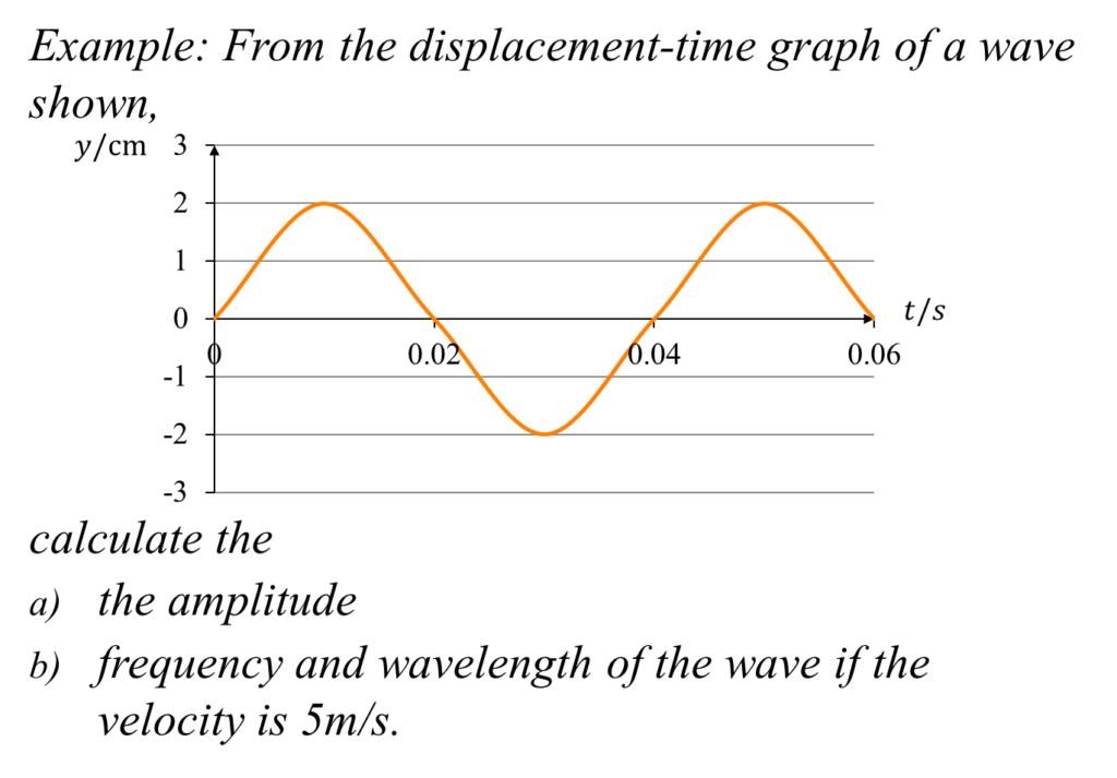
Amplitude = maximum displacement = 2cm
Period (T) = time taken for one cycle = 0.04s
f=1/T⇒f=1/0.04=25Hz
Wavelength λ =v/f=5/25=0.2m
Equation of a travelling wave
Compare the general representation of a wave with a sine wave*
The equation of a travelling wave can be represented as
y=A sin〖(ωt-kx)〗
Where A is the amplitude
ω=”angular frequency” = 2πf
k=”wave number”=2π/λ
We may substitute and write the equation as
y=A sin〖(2πft-2π/λ x)〗
y=A sin〖(2πft-2π/λ x)〗
y=A sin(2πfλ/λ t-2π/λ x)
y=A sin〖2π/λ(vt-x)〗
Whichever equation is mastered is okay but the initial equation is suggested.
The important thing to know in all these equations is the coefficient of t(=ω) and x(=k) not the sign.
Example: A travelling wave is represented by the equation y=0.2 sin〖(30x-4t)〗 where the symbols have their usual meanings. Find the
i) amplitude ii) wavelength iii) frequency iv) period v) speed of the wave
y=0.2 sin〖(30x-4t)〗
y=A sin〖(ωt-kx)〗
A=0.2m
ω=2πf=4
f=4/2π=0.64 Hz
Progressive and stationary wave
Waves which spread out continously are called travelling or progressive waves.
A stationary wave is obtained when two progressive waves of equal amplitude and frequency are travelling in opposite directions.
*
Most stationary waves are obtained as a result of reflection of the incident wave. The incident wave and the reflected wave now form a stationary wave.
A node (N) is a point on a stationary wave where there is no movement of the medium. An antinode (A) is a point of maximum movement of the medium.
Examples of stationary waves include waves obtained by plucking a string fixed at both ends. The transverse waves travel both ways along the string and is reflected at the fixed ends.
Waves set up in open and closed pipes are stationary (longitudinal) in air.
*
Longitudinal stationary waves produced from wind instruments like flute, trumpet, saxophone form musical notes. Transverse stationary waves produced musical notes in stringed instruments such as guitar, piano etc.
Properties of waves
Waves show the following properties or characteristics: reflection, refraction, diffraction, interference, polarization.
1) Reflection
This is the ability of waves to bounce back to the same medium when they encounter an obstacle or a surface.
*
All waves undergo reflection

2) Refraction
This is the change in the speed and direction of the waves as they move from one medium to another
*
During refraction, the frequency of the wave remains the same but the wavelength and wave speed changes.
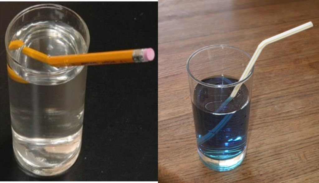
3) Diffraction
This is the ability of waves to bend around obstacles or spread out when they pass through narrow openings.
*
We can hear noise from another classroom or simply at the other side of a building or mountain because the sound waves have bent around the obstacles
*
Diffraction occurs when the wavelength of the incoming wave is longer than the width of the opening or size of the obstacle
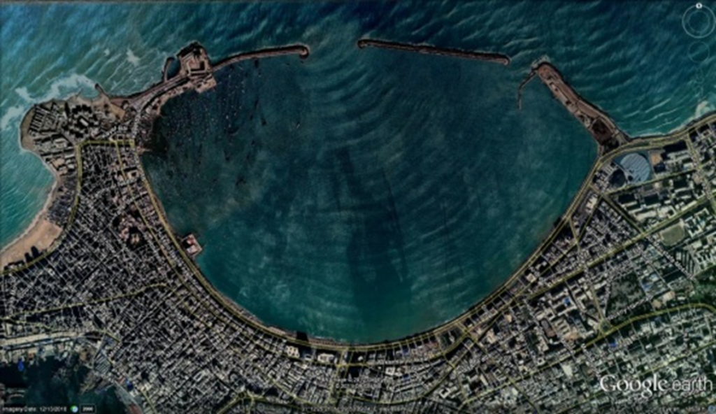
4) Interference
This is the effect produced when two waves of the same frequency, amplitude and wavelength travelling in the same direction are superimposed (placed one top of the other). They are two types of interference;
i) Constructive interference: If the two waves have travelled the same distance, or if one wave has travelled further than the other by a whole number of wavelength, then the combined wave will have twice the amplitude of the others
ii) Destructive interference: if one wave is ahead of the other by λ/2 (half wavelength), such that the crest of one wave arrive at the same time of the trough of another, the resultant wave will have a zero magnitude
*
5) Polarization
We know that a transverse wave is one in which the vibration is perpendicular to the direction of propagation of the wave. In a string wave, the elements of the string move in a plane perpendicular to the string. Thus plane-polarization occurs when the vibrations of particles of a transverse wave remain parallel as the wave propagates.
*
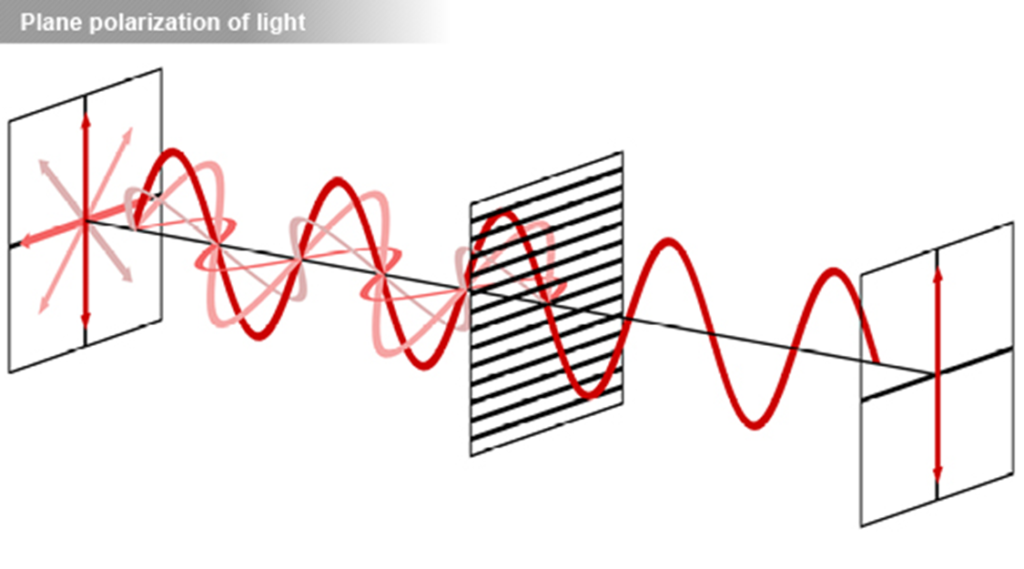
NOTE that only transverse waves (e.g. light waves) can be polarized. Longitudinal waves (e.g. sound waves cannot be polarized.
Polarization of light
i)Polarization by tourmaline crystals: unpolarized light can be made to pass through polarizers such as tourmaline crystals, quartz or a manufactured material called polaroid to produce plane-polarized light.
ii.Polarization by reflection: it has been found that when unpolarized light is incident at an angle of 570 on a polished glass surface, the reflected light is plane-polarized
*
Applications of polaroids
1)The polaroid is used in sunglasses and windscreens to reduce the intensity of incident sunlight.
2)It is also used to eliminate light glare as a result of reflection from glass doors, window panes, and from the road ahead on a sunny day
LIGHT WAVES & OPTICS
Light and its sources
The study of optics is very important in the field of physics. Light is a wave that carries energy. Light as a wave does not require a material medium for propagation. No medium is required for us to receive light from the sun.
There are different sources of light
Luminous objects: These are objects that give off light on their own. It includes the sun, stars, fire flies which are natural sources and lamps, fires, candles etc., that are man-made sources of light.
Non-luminous objects: These objects do not give off light by themselves but reflect the light from luminous objects for example the moon. The moon is seen by reflection of the sun rays from its surface. Also a book, a person’s face and most objects are non-luminous objects. We are able to read the print from a book during daylight because light from the sun falling on the page is reflected by the white page but absorbed by the black print.
Transmission of light
Light is transmitted through a vacuum. The path travelled by light is called a light ray. A collection of light ray is called a beam. A light is indicated by a straight line with an arrow head.

There are three types of beams
Parallel beam

Convergent beam

Divergent beam

Rectilinear propagation of light
It can be demonstrated that light travels in a straight line.
Place an illuminated lamp L in front of a small hole A punched on a piece of cardboard. Move two other pieces of cardboards B and C until the light through A is seen.
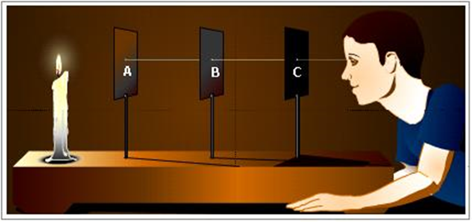
If we pass a thread through holes A, B and C and the thread is held taut, it is straight showing that the three holes are in a straight line.
This phenomenon is described as the rectilinear propagation of light.
This is what is responsible for the formation of shadows and eclipses and the operation of the pin-hole camera
Shadows
A shadow is produced when light is obstructed by an opaque object. When light falls on this opaque obstacle, the rays just grazing its edges form the outline of a shadow. The shade under a tree or canopy is as a result of the obstruction of sunlight.
The kind of shadow formed depends on the size of the source of illumination.
A point source of light produces a sharp shadow while a large source of light produces a full shadow (umbra) and a partial shadow (penumbra)
Types of objects with respect to optics
1)Transparent: these are objects that allow light to pass through them and objects can be clearly seen. E.g glass
2)Translucent: these objects allow light to pass through them but objects cannot be clearly seen. E.g. tinted glass
3)Opaque: they do not allow light to pass through them and objects cannot be seen e.g. book, stone
blue cup – opaque, green cup – translucent, and transparent cup

Eclipses
The earth and the moon are opaque objects. The sun being a luminous body i.e. producing its own light illuminates certain parts of the earth at certain times. The moon revolves round the earth, and the earth also revolves round the sun.
At particular times during these movements, all three bodies lie on a straight line. If the moon is between the sun and the earth at this time, people in certain places of the earth cannot see the sun; a solar eclipse or eclipse of the sun is formed.
*
If the earth is between the sun and the moon, it is referred to as eclipse of the moon or lunar eclipse.
*
Annular eclipse: this occurs when the earth and the moon are in positions where the end rays of the sun intersect before reaching the earth. A ring of light is formed around the moon
*
Annular eclipse provides astronomers an opportunity to study the outer part of the sun.
Pin-hole camera
This was the camera used in the 15th century. It consists of a light-tight box; one end has a small hole made with a pin or needle-point. The opposite end has a photographic paper or film. Its operation makes use of the fact that light travels in straight lines. Light from an object in front of the pin-hole passes through the hole and forms an inverted image on the film since the amount of light entering the camera is small.
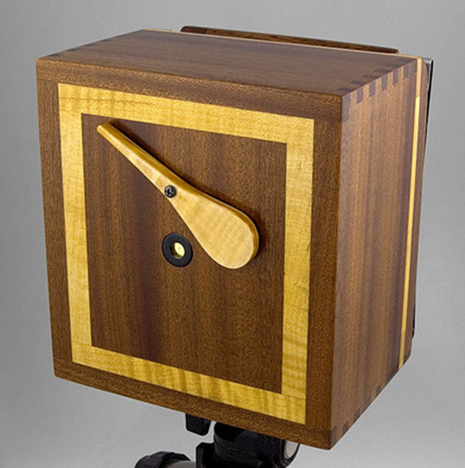
If the hole is bigger, a brighter but blurred image is produced.
If the distance between the object and the hole (O_d) is increases greater than the image distance (I_d), then the image is diminished. On the other hand, the image is enlarged when the image distance I_d (from the pin-hole to the film) is greater than the object distance O_d (object to pin-hole).
With many pin-holes or a wide hole, the image becomes blurred. Each pin-hole produces its own image on the screen and the overlapping of the image producing blurring.
Magnification
This is the ratio of the image distance to the object distance or the image height to the object height.
“magnification” m=(image distance)/(object distance)=(image height)/(object height)
m=I_d/O_d =I_h/O_h
Magnification has no units
For a pin-hole camera, the length of the camera is the image distance.
Example: The length of a pin-hole camera is 15cm. It is used to photograph an object 60cm away from the hole and 90cm high. Calculate the object of the image and magnification produced
Magnification m=(image distance)/(object distance)=(length of camera)/(object distance)
=15/60=0.25
m=(image height)/(object height)⇒0.25=I_h/90
I_h=90×0.25=22.5″cm”
Reflection of light at plane surfaces
When light falls on a surface, it is either absorbed, transmitted or reflected. Sometimes a combination of the processes occur. If the surface is highly polished or shinny, then the light rays will be reflected. The rays which strike the surface are referred to as incident rays while the rays thrown back from the surface are reflected rays.
There are two types of reflection: regular and irregular reflection
Regular reflection: Parallel rays of light that are incident on a surface that is smooth or polished are reflected as parallel rays in one direction.
Mirrors produce regular reflection
Scattered/irregular or diffused reflection: In this type of reflection, parallel rays of light are incident on a rough surface such as the surface of a book or cloth and are reflected in different directions.
Laws of reflection
1)The incident ray, the reflected ray and the normal all lie on the same plane.
2)The angle of incidence is equal to the angle of reflection
Image formation by a plane mirror
The characteristics of the image formed by a plane mirror are as follows:
1)The image is the same size as the object
2)It is as far behind the mirror as the object is in front
3)The image is laterally inverted
4)It is virtual
5)It is upright or erect
Number of images formed by inclined mirrors. When an object is placed between two inclined mirrors, a number of images are formed depending on the angle between the mirrors. Let us consider an object O placed between two mirrors M_1 and M_2 inclined at an angle θ=90^0 to each other. An observer sees three images of the object.
In general, the number of images formed by inclined mirrors is related according to the formula
n=360/θ-1
Where n is the number of images and θ the angle between the two mirrors.
When θ=180^0, the two mirrors act as a single mirror and only one image is formed
When θ=0^0, that is when the two mirrors are parallel, an infinite number of images are formed (n=360/0-1=∞)
You may have noticed an infinite number of images in a saloon where dressing mirrors are placed at opposite sides of the wall.
Effect of mirror rotation on a reflected ray
Let us fix an incident ray at an angle i to a plane mirror MNK. The angle of reflection is also i. The angle between the incident ray and the reflected ray (ONR) is the sum of the incidence angle and reflected angle “i.e”.” ” i+i=2i.
If the mirror is now rotated through an angle θ (the incident ray remaining fixed), the normal is also rotated through θ. The new angle of incidence is now i+θ and consequently, the angle of reflection is i+θ.
The angle in this case between the incident ray and the reflected ray is i”+” θ+i”+” θ=2i+2θ The angle of rotation of the reflected ray is 2i+2θ-2i=2θ
If the incident ray is fixed and a plane mirror is rotated through an angle θ, the reflected ray is rotated through an angle 2θ.
Applications of plane mirrors
1)Plane mirrors are used as dressing mirrors and inner driving mirrors
2)They are used in making simple periscope: a device used to view objects above a barrier or obstacle that is hidden from direct view.
The periscope is used in armoured tanks by soldiers to see above the armour plating outside
The simple periscope has a major disadvantage in that it produces multiple images.
3.Kaleidoscope: This is a children’s toy that produces multiple images based on the principle of inclined mirrors.
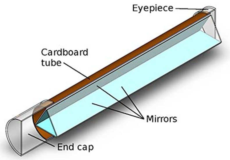
Mirror galvanometer: a plane mirror is used to measure small angles of rotation of the coil in this galvanometer that measures very small electric currents
A plane mirror is used in the sextant: a navigation instrument for measuring the angle of elevation of the sun.
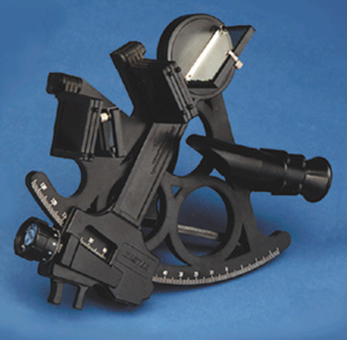
CURVED MIRROR & LENSES
REFLECTION OF LIGHT BY CURVED MIRRORS
Apart from plane mirrors, curved mirrors also have many important scientific and practical uses.
There are two main types of curved mirrors
a)Concave or converging mirror
b)Convex or diverging mirror
A curved mirror is formed by cutting out a part of a sphere made of glass and one side is silvered.
If the inside surface of this spherical part is painted silver and the outside part becomes the reflected surface, we have a convex or diverging mirror.
*
If the outside surface is silvered and the inner surface is the reflecting part, we have a concave or converging mirror.
*
DON’T FORGET: a concave mirror is also called a converging mirror.
Then a convex mirror is called a diverging mirror
Terms used in curved mirrors
Apperture: this is the width AB of the mirror.
Pole(P): it is the centre of the reflecting surface of the mirror
Centre of curvature(C): this is the centre of the sphere from which the mirror part was taken.
Principal axis is the line PC from the pole to the centre of curvature.
Radius of the curvature (r):it is the distance CP from the centre of curvature to pole.
Principal focus(F) of a concave mirror is the point at which all incident rays parallel and close to the principal axis converge after reflection.
The principal focus of a convex mirror is the point at which all rays parallel and close to the principal axis appear to diverge after reflection.
The principal focus is said to be a real focus because reflected rays actually pass through it. If a screen is placed at this point, a bright spot of light is obtained. On the contrary, the principal focus of a convex mirror is virtual as reflected rays do not pass through; no image is formed on a screen placed at this point.
This is why we say that it appears to diverge from this point.
Focal length (f): this is the distance FP – from the principal focus to the pole of a curved mirror.
It is found by measurement and experiment that
f=r/2
Focal length is half of the radius of curvature for both types of mirrors
Formation of images of a curved mirror
The size, position and nature of the image formed by a curved mirror depends mainly on the position of the object from the pole of the mirror (object distance).
*
Convex mirror images
If the concave mirror is replaced with a convex mirror, an image that is smaller than the object, upright and virtual is produced for any position of the object.
A quick way to remember this is by using the acronym SUV: Smaller Upright Virtual
Ray diagram of images
The images obtained from curved mirrors can always be drawn to scale using a ray diagram.
The object O is drawn to scale as a straight line with an arrow-head perpendicular to the principal axis. We can also represent the mirror by a perpendicular straight line.
The image is found by the intersection of any two out of the following three rays that occur
1.A ray parallel to the principal axis passes through the principal focus F after reflection.
2.A ray through the centre of curvature strikes the mirror and is reflected back along the same path.
3.A ray through principal focus F strikes the mirror and is reflected parallel to the principal axis.
*
When the object is placed between the pole P and principal focus F,
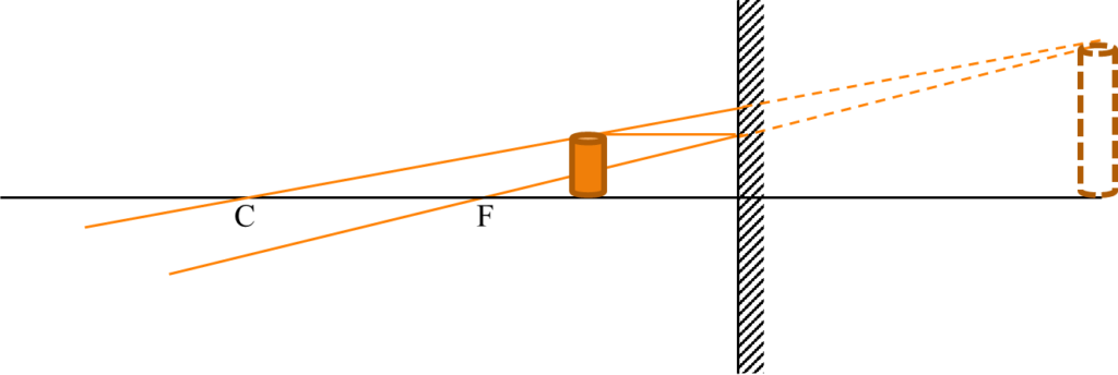
the image is virtual, magnified and upright.
Determination of focal length of curved mirrors
1)Quick but approximate method:
A quick method is the use of a concave mirror to focus the image of a distance object such as the window of a room or lab on a screen which may be the wall. The mirror is adjusted until a sharp image is seen on the wall.
The distance between wall and the mirror gives an approximate value of the focal length of the mirror, the ray will converge at the principal focus
2) Focal length from measurement of radius of curvature
An illuminated object (cross wire) from a ray box is placed in front of a concave mirror mounted on a wooden stand. The mirror is moved front and back until a sharp image is obtained on the front surface of the ray close to the cross wire. The distance between the mirror and the cross wore object gives the radius of curvature, r, of the mirror.
The focal length, f, is then given by f=r/2
The experiment should be repeated two or three times and the average of the radius of curvature obtained from each procedure is then used to obtain the focal length
3) Mirror formula
The objet distance, u, the image distance v and the focal length f of a curved mirror have been shown to be related according to the equation
1/u+1/v=1/f
This equation can be used to obtain the focal length of a concave mirror
Mirror formulae: sign convention
When the mirror formula is used 1/u+1/v=1/f, f=r/2, it is necessary to use positive (+) of negative (-) sign to each of the distances according to a sign rule.
The two common sign conventions are shown.
Real-is-positive
1) All objects are real so object distance u is always positive. If image is real, then image distance v is positive.
2) Virtual images are at a negative distance from the mirror
3) A concave mirror has a real focus so focal length f is therefore positive.
4) A convex mirror has a virtual focus hence its focal length f is negative.
New Cartesian
1) Distances measured to the right are positive
2) Distances measured to the left are negative. The object is always placed on the left of the mirror
3) A concave mirror has a real focus which is left of the mirror. Hence its focal length is negative
4) A convex mirror has a virtual focus which is right of the mirror. Its focal length is positive.
If any of these sign conventions is used, it must be used consistently
The first sign convention (Real-is-positive) is recommended
Magnification
The magnification of a mirror is given by
m=v/u=(image distance)/(object distance)
Example: An object is placed 15cm in front of a concave mirror of radius of curvature 20cm. Calculate the position, nature and magnification of the image produced.
| Real-is-positive | New Cartesian |
| u=+15, f=r/2=20/2=+10 (concave mirror) From mirror formula 1/u+1/v=1/f, 1/15+1/v=1/10 1/v=1/10-1/15=1/30 v=30 Since this is a positive distance, it means that the image is real. m=v/u=30/15=2 | u=-15 concave mirror has a real focus, thus f=-20/2=-10 Mirror formula: 1/u+1/v=1/f 1/(-15)+1/v=1/(-10) 1/v=-1/10+1/15=-1/30 v=-30 So the image is formed 30cm on the left, the same side as the object and is therefore real m=(-30)/(-15)=2″(same result)” |
Example: An object is placed 12cm in front of a diverging mirror and an image is produced 3cm behind the mirror. Calculate the focal length of the mirror.
Using real-is-positive sign convention,
Diverging mirror = convex mirror, u=+12, v=-4
(because a convex mirror ALWAYS produces a virtual image)
From 1/u+1/v=1/f, 1/12-1/4=1/f
1/f=-2/12
f=-6cm
The negative sign is a confirmation that the focus is virtual which typical of a convex mirror
Applications of curved mirrors
CONCAVE
1) Concave mirrors are used as shaving (or dental) mirrors because a man sees an enlarged image (erect and virtual) of his face when he places his face near the mirror (between the principal focus and the pole)

2) They are used as reflectors in reflecting telescopes
3) They are used in microscopes
CONVEX
4) Convex mirrors are used as side mirrors in cars because they give an erect image of an object behind the driver or for observing traffic behind. In addition, such mirrors provide a wide range of view.
These mirrors however give a false impression of the distance between the object behind and the driver.
These days, a warning sign is usually printed on the side mirrors that reads like “OBJCTS ARE CLOSER THAN THEY APPEAR”
PARABOLIC
5) These special types of curved concave mirrors are used in car headlamps and search lights because they produce parallel beams of light.
LENSES
A lens is a transparent glass material of thickness varying from the middle to the edges with a curved surface on one or both sides. It causes a beam of light to converge or diverge.
Lenses have many important uses to science and life
Types of lenses
There are two kind of lenses
1) Converging or convex lens
2) Diverging or concave lens
1) Converging lens: these lenses are thicker at the centre than at the edges. They make parallel beam of light converge at a point. The various types of converging lens are shown
*
2) Diverging lens
It makes parallel bea, of light appear to diverge from a point. They are thinner at the middle than at the edges.
Lenses which are biconcave or biconvex are the common ones used in the laboratory. Plano-concave and plano-convex are used in optical instruments as they have only one curved surface.
Converging or diverging meniscus lenses are used as contact lenses to correct certain eye defects because they fit the curvature of the eyeball
Our study is primarily on biconvex or biconcave. The human eye has a natural converging lens that is biconvex.
Definition of terms used to describe a lens
Optical centre C is the point through which light rays pass without being deviated by the lens.
Principal axis is an imaginary line through the optical centre that joins the midpoint of the opposite faces of the lens
Principal focus F of a converging lens is the point on the principal axis to which all rays parallel and close to the principal axis appear to converge after refraction through the lens
Principal focus F of a diverging or concave lens is the point from which all rays parallel and close to the principal axis appear to diverge after refraction through the lens
*
Note that the principal focus of a converging lens is on the other side from the incident rays, while that of a diverging lens is on the same side as the incident rays and the rays do not actually pass through it.
From the rays diagrams, we see that
Focal length f is the distance from the principal focus to the optical centre of a lens
The power of a lens P is the reciprocal of its focal length f when it is measure in metres.
p=1/f , f is in metres
Unit of power is dioptres
The shorter the focal length, the greater the power of the lens
Determination of the focal length of a converging lens
1) Quick but approximate method
Hold the lens near the back of a room or lab and move it until a sharp image of a distant object e.g. window panes is formed on a sheet of paper (screen) or the wall.
Measure the distance from the lens to the paper. This distance is approximately equal to the focal length f of the lens
2) Plane mirror and illuminated object method
Mount the converging lens on a holder and place a plane mirror behind it (both should be vertical). An illuminated object e.g. cross wire from a ray box is placed in front of the lens. This object is adjusted by moving to and fro until a sharp image is obtained on the surface beside the illuminated object. The distance from the object to the lens gives the focal length
3) Lens formula
The lens formula is given by
1/u+1/v=1/f
Where u is the object distance
v is the image distance and f is the focal length
Determine first an approximate value of the focal length f using the method described in 1.
Now place an illuminated object from a ray box at a distance of about 1.5f in front of the lens.
Adjust the screen behind the lens until a sharp image of the object is formed. Measure the exact distance of the illuminated object to the lens u and the distance from the screen to the lens v
Repeat the experiment for four other values of u
Now apply the lens formula to get values for f for each value of u and v.
The average of the values of f gives the focal length of the lens.
Alternatively, plot a graph of 1/u against 1/v. The intercept on either axis gives the value for 1/f. Hence the reciprocal of this intercept gives the focal length.
Ray diagrams in lenses
If we know the focal length and the object distance, we can determine the position and nature of the image by scale drawing of the ray diagram. Three rays can be used to obtain the image. They are
i) a ray from the object, parallel to the principal axis and converges to the principal focus after passing through the lens
ii) A ray from the object that passes through the optical centre without deviating or converging
iii) Ray through the principal focus and emerges parallel to the principal axis after refraction through the lens.
When constructing ray diagrams, we represent the object and lens by a straight line perpendicular to the principal axis. The object and image line should have an arrow head.
*
Example: An object is placed 20cm in front of a converging lens of focal length 15cm. Find by scale drawing
i) the image distance
ii) Its magnification and description of the image
Lens formula and sign convention
Two sign conventions are used in the application of the lens formula
Lens’ formula: 1/u+1/v=1/f
Real-is-positive
1/u+1/v=1/f
Object distance u is always positive
f is positive for converging lens and negative for diverging lens
Virtual image has v as negative
New Cartesian
1/v-1/u=1/f
u is always negative as the object is placed on the left side of the lens
f is positive for a converging lens and negative for a diverging lens
Distance to the left are negative while distance to the right are positive.
It is suggest to the student to adopt and learn the Real-is-positive sign convention
Magnification =(image height)/(object height)=((image distance))/(object distance)=v/u
Example: An object is placed 10cm from a converging lens of focal length 15cm.
(i) Calculate the image distance and state the nature of the image.
(ii) What is the power of the lens?
Using Real-is-positive sign convention
u=10(converging lens), f=+15
From lens formula, 1/u+1/v=1/f
1/10+1/v=1/15
1/v=1/15-1/10=-1/30
v=-30cm
This means that the image is formed 30 cm in front of the lens (the same side as the object). It is virtual, magnified and upright.
Note that when a virtual image is formed in a converging lens, it is erect or upright not inverted like a real image
New Cartesian
u=-10, f=+15
1/v-1/u=1/f
1/v-(-1/10)=1/15 → 1/v+1/10=1/15
1/f=1/15-1/10=-1/30
v=-30cm (same result)
Power P=1/f, but f=15/100=0.15m
P=1/0.15=6.7dioptres
From the lens formula, 1/u+1/v=1/f, multiply through by v: v/u+v/v=v/f
m+1=v/f
Example: The image in a convex lens is upright and magnified four times, calculate the object distance if the focal length is 20cm.
m=v/u=4 → v=4u
f=20cm
It is given that an upright image is formed. This means that the image is virtual and using Real-is-positive sign convention and lens formula,
1/u+1/v=1/f
1/u-1/4u=1/20
(4-1)4u=1/20 → 3/4u=1/20
4u=3×20
u=60/4=15cm
Take care with the signs
Application of lenses: optical instruments
Microscope: simple and compound microscope
The microscope is used for enlarging the image of a small object not easily seen with the human eye.
The simple microscope is a magnifying glass. It is used for reading small print and for observing specimens in biological studies. It consist of a converging lens with a handle
*
When the object is placed between the principal focus and the centre of the lens, an enlarged erect and virtual image is seen.
The shorter the focal length, the greater the magnifying power of the lens
*
Normally, the human eye can see objects distinctly when it is at a distance of 25cm and beyond. A very small object placed at 25cm from the eye is however not easily seen due to the small visual angle. When a magnifying glass is used and brought closer to the eye, the clear magnified image of the object is now seen at about the 25cm point.
SOUND WAVES
Sound is a form of energy. It is a form of wave that is conveyed from a vibrating body to a listener through a medium. Sound waves are mechanical waves in that they require a material medium to travel. Sound waves are also longitudinal waves in that the direction of travel of the vibrating source is parallel to the direction of propagation of the wave
When a train is approaching a station, we hear the vibration of the rails before the train comes to sight
The metal (solid) of the rail carries the sound and we hear it with our ears through the air (gas)
Transmission of sound
It will be shown that sound waves cannot travel in a vacuum (empty space)
*
Suspend an electric bell in a glass jar. The base and the top of the jar is sealed with grease to make it airtight. A vacuum pump is connected to the jar.
When the bell is connected to a battery and switched on, we hear the bell ring because there is still air in the jar. Now switch on the pump to remove the air and the sound dies down. The clapper is still seen to be vibrating but no sound is heard.
The clapper is seen vibrating because light can travel in a vacuum but sound cannot be heard because sound cannot travel in a vacuum.
This is the reason astronauts communicate to each other through radio waves (a form of light waves) even when they are close together because there is very little atmosphere on the moon or in space
Propagation of sound waves in air
Sound waves travel through air by the displacement of air particles
*
Velocity of sound waves
It has been stated in waves previously studied that the wavelength λ, frequency f, and wave speed v are related according to the equation
v=fλ
This is also true for sound waves
Example: Calculate the velocity of the sound wave produced when a note having a frequency of 100Hz and a wavelength 0.33m is played.
v=fλ
f=100Hz, λ=0.33
v=1000×0.33=330ms^(-1)
The velocity of sound waves is however different in different media. It varies with the density or elasticity of the medium. In air, the speed of sound is about 330ms^(-1). In water, sound travels at about 1500ms^(-1), while in a metal, it has a speed of about 5000ms^(-1). Temperature, wind direction also affect the velocity of sound.
During a thunderstorm, we see a flash lightning before we hear the accompanying sound of thunder because light travels faster than sound. The speed of light is about 3×10^8 ms^(-1) (300,000,000ms^(-1)) compared with 330ms^(-1) for sound.
So if the thunder is heard 6s after the lightning is seen, it means the storm is about 330×6≅2km away
Reflection of sound
Sound wave just like light waves can be reflected when they strike a surface or an obstacle. The laws of reflection of light waves hold true for sound waves. Reflection of sound produces echoes.
An echo is the sound heard after the reflection of sound waves from a plane surface.
If you stand close to wall and clap your hands, the sound waves hit the wall and bounce back, and you hear the sound a second time. If you shout in an empty room or hall, you also hear the echo.
Echoes can sometimes constitute a nuisance and be undesirable but in some other cases they are very helpful and have important applications.
Listening to speech of music outdoors can be uninteresting as the loudness dies off with distance. If the echo is not controlled in a n auditorium or record studio, reflection of sond can occur from the walls, floors, ceiling leading to the production of multiple echoes and it confuses the listener. This continuous occurrence of echoes is called reverberation.
Reverberation is reduced by padding the ceiling and walls with soft perforated bords to minimize the reflection of sound.
Application of echoes
1. Determination of speed of sound in air
Echoes can be used to determine the speed of sound in air by directing a sound wave to a large high wall and measuring the time taken for the sound to return to the sender after hitting the wall
*
2. Echo sounding devices
a) Depth sounding: ships are able to determine the depth od the sea by sending a sound signal down to the sea bed and detecting with a receiver the time the echo is received after reflection from the sea bed.
The velocity of sound in water is known v_w, then depth d is given by
d=(v_w t)/2
b) Exploration of oil and other mineral resources
Geophysicists make use of echoes in the exploration of oil and gas. By setting off an explosion below the earth’s surface, the resulting sound produced is reflected by underground layers of rock at different rates depending on the nature and thickness of the rock
Interpretation of these results will reveal to the scientist possible oil-bearing rock formation or mineral resources
c) Detection of submarine
Echo sounding devices sometimes referred to as sonar is used in detecting enemy submarines or large objects in water or even a school of fishes.
Sound effects
Interference of sound
When two similar sources of sound interfere constructively, a loud sound is produced due to a combination of the amplitude of each of the sound wave.
When they interfere destructively, no sound is heard because the crest of one of the sound wave falls on the trough of the other and their effect cancel each other
Beats
When two sound waves with slightly different frequencies combine, the amplitude of the resulting wave will have a maximum and a minimum. The intensity of the sound produced rises and falls with time. These alterations in the loudness with time give rise to beats.
The intensity is proportional to the square of the amplitude. This process is termed waxing and waning.
The periodic variation in the loudness of a sound heard when two notes of nearly equal frequency are played simultaneously is called beats.
If the frequencies of the sound waves are f_1 and f_2, the beat frequency f is given as the difference between the frequencies of the two waves i.e. 〖f=f〗_2-f_1
Example: two notes of frequency 132Hz and 128Hz are sounded simultaneously, calculate the frequency of the beat produced
Beat frequency f=f_2-f_1=132-128=4Hz
Uses of beats
1. Beats are used to determine the frequency of a tuning fork. When a tuning fork of known frequency f_k is sounded together with a fork of unknown frequency f_u and the beat frequency f is measured, the unknown frequency can be calculated using the relation f_u=f_k+f
2. Beats are also used to tune musical instruments e.g. a piano
In achieving this, a piano tuner listens for beats when he strikes a particular key on the piano and the sound produced from a standard tuning fork. If no beat is heard, it means the piano has been tuned. If not, the tension in the string is adjusted
Doppler effect
This is the change in frequency (pitch) of a source when there is relative motion between the source and the observer. This phenomenon occurs both in light and sound waves
You notice that the sound from a train or the siren from a police car increases as it approaches towards your direction. After it passes you, there is a sudden drop in the pitch. This is the doppler effect.
*
Characteristics of sound
It is necessary to understand some fundamental characteristics of sound especially in music.
1. Pitch
The pitch of a note is its position on the musical scale. Pitch is that characteristic that differentiates a high note from a low note. The pitch of a note depends on the frequency of the sound wave. In a piano, the right hand keys produce notes of high pitch than the left hand keys
A tight string produces a higher pitched or higher frequency sound when plucked than a loose string.
The sounds from young boys or girls can be differentiated from that of older people during an event because the young boys have a relatively higher pitched voice
Generally, the human ear can hear sounds conveniently between 400Hz to about 20,000Hz. Some animals such as dogs, cats can hear notes of much higher frequency
2. Loudness or intensity
Intensity of a sound is the rate of flow of energy per unit area perpendicular to the direction of the sound wave. Loudness is a sensation in the mind of a particular observer. It depends on the intensity of sound. Since intensity depends on amplitude, loudness is also a function of amplitude.
*
Loudness also depends on the mass of air which can set into vibration
When the prongs of a tuning fork are vibrated in the air, only a small ass of air vibrate and a soft sound is heard. The sound is however observed to be loud when the vibrating prongs are now set on a table. This is because a large mass of air in contact with the surface of the table is now set into vibration
The strings on a violin or guitar are not at all loud when set into vibration on their own.
*
This is why they are attached to a sounding box of large surface area.
This is also the principle of a loud speaker.
The ear must be placed close to a telephone ear piece to hear the sound distinctly. This is because of the small mass of air displaced by the circular metal plate inside. A large sound is however heard from a loud speaker as a result of the large surface area of the vibrating core
Quality or tone
This is the characteristic of a note that distinguishes it from another note of the same pitch and loudness.
A well-made and good quality tuning fork can produce a pure note with a single frequency.
A musical instrument never produces a note of single frequency; notes of higher frequencies usually accompany the fundamental frequency. These higher notes are called overtones or harmonics.
For example, when a note of 200Hz is played on a guitar, overtones of frequencies 400Hz, 1000Hz, 1600Hz may accompany it. The amount of overtones differs for the same frequency note played on different musical instruments so they produce notes of different quality.
These different overtones provide a background which makes us able to distinguish this same note when it is played on a piano.
Harmonics are frequencies which are multiples of the fundamental frequency.
An octave of a note is a note of twice the frequency. E.g. the octave of 512Hz is 1024Hz
Ultrasonic sound
The human can detect sound frequencies ranging from 20Hz to 20,000Hz. Frequencies in the range of 10^5Hz are called ultrasonics. They cannot be detected by the human ear and are useful in
a) Destroying bacteria in water
b) Removing smoke from air
c) Cleaning metals
d) Drying papers
e) Hospitals to determine the sex of the baby for an expectant mother
Forced vibrations and resonance
If a body vibrating at a particular frequency is placed in contact with another body, it will cause it to vibrate at the same frequency of the former. The vibration of the second body is said to have been forced.
Some examples of forced vibrations include
1. The vibrating body of a violin or guitar as a result of the vibrations of the strings
2. The vibrations of the cone of a loud speaker caused by the fluctuation in the current flowing in the voice coil.
Resonance
Resonance is a special effect of forced vibrations. It is an effect caused by a vibrating body setting another body vibrating with both having the same natural frequency.
When a body is set into vibration and left to vibrate on its own, the body will vibrate with its own natural frequency
When the frequency (forcing) of a vibrating body A acting on another body B’s natural frequency, the resulting effect is an induced vibration with very large amplitude. Resonance has occurred.
Vibrations in strings and pipes
When the string of musical instrument such as a violin is plucked, a transverse wave travels along the vibrating string. This wave is reflected back at the fixed ends. We then have an interference of two waves travelling in opposite directions and a stationary transverse wave is set up.
*
The points at B and C of the stationary wave are called nodes because they cannot move while point A is referred to as an antinode because there is maximum movement at this point where the string vibrates in a single loop.
This mode of vibration is called the fundamental mode of vibration because the string produces a sound of the lowest possible frequency (fundamental frequency)
The distance between the two consecutive nodes is half wavelength or λ/2 and this is equal to the length of the string l. i.e.
l=λ/2 and λ=2l
From wave formula, v=fλ, we can deduce that the fundamental frequency f_0 produced is given by f_o=v/λ=v/2l
Harmonics or overtones in strings
Higher frequencies which are integral multiples of the fundamental frequency are called harmonics or overtones.
Note that f_o is the first harmonic but the first overtone may be 2f_o or 3f_o depending on the case.
In the case of a string fixed at both ends, harmonics are obtained by touching the wires slightly (damping) at centre O. and simultaneously plucking it at P such that the length BP is one-quarter of the length l of the string.
The string vibrates in two loops. There are now 3 nodes B, O and C.
Since BO=OC=λ/2, then BC=BO+OC=λ/2+λ/2=l
λ=l
*
The frequency of the first overtone or second harmonic is then given as f_1=v/λ=v/l
l=λ/2+λ/2+λ/2=3λ/2
λ=2l/3
f_2=v/λ=v/(2l/3) or 3v/2l
First harmonic: fundamental frequency: f_o=v/2l
Second harmonic, first overtone f_1=v/l=2f_o
Third harmonic, second overtone f_2=3v/2l=3f_o
Third overtone f_3=2v/l=4f_o
And so on
A slight difference exist between harmonic and overtone:
All harmonics are whole number multiples of the fundamental frequency. However, higher frequencies which may or may not be whole number multiples of fundamental frequency are called overtones
The overtones in a bell for example are not harmonics because their frequencies are not higher multiples of the fundamental frequency
Example: A metal wire of mass 2g and length 0.5m is held under tension by a weight of 8kg.
i) Compute the fundamental frequency
ii) Compute the first and second overtones
iii) Find the speed of a transverse wave produced in the string
f_o=1/2l √(T/M)
l=0.5, M=(2×10^(-3))/0.5, T=8kg×10ms^(-2)=80N
f_o=1/(2×0.5) √(80/(4×10^(-3) ))
Example: a length of wire has a frequency of 255Hz when stretched by a force of 225N. If the fore increases to 324N, what is the new frequency of vibration?
f∝√T
f=k√T → 255=k×√225
255=15k
k=17
f=17×√324=17×18=306Hz
Vibrations in open and closed pipes
When one end of a tube is closed, it is termed a closed pipe. When both ends are open; an open pipe.
Pipe organs, flutes, saxophones, trumpets etc all produce their characteristic sounds when the air inside them is made to vibrate.
When air vibrates in a pipe, the waves produced are reflected at the ends producing a longitudinal stationary wave along the length of the pipe. The air particles at the end of the pipe are unable to move so a node is formed. At the open end, the particles now move with maximum amplitude – an antinode point.
*
Vibrations in a closed pipe
The simplest form of vibration i.e. the fundamental mode of vibration for a closed pipe can be shown in a resonance tube experiment.
The frequency of the tuning fork is f_o. The fork is made to vibrate over the top of the tube l * initially small and water is now let out slowly from the bottom tap.
The first loud sound that occurs means that resonance has occurred.
*
This means that the air column has the same frequency as the tuning fork and a stationary wave is produced from the combination of the incident and reflected wave.
The water level is the closed end where the node is formed and the antinode is at the open end.
The length of air column from top to water level is l_1 and this equal to one-quarter the wavelength i.e. the distance between anti-node and a corresponding node
l_1=λ/4 → λ=4l_1
From f=v/λ, f_o=v/(4l_1 ) where f_o is the fundamental frequency and v is the velocity of the wave.
By varying the length of the air column that is by letting more water out, a second position is reached where a large sound is heard again.
At this level, distance from antinode to node and to another node
l_2=λ/4+λ/2=3λ/4
f_1=v/λ=4/(4l/3)=3v/4l or 3f_o
Third harmonic, first overtone
Possible harmonics in a closed pipe will therefore be f_o. 3f_o, 5f_o, and so on.
NOTE: only odd harmonics are present
Vibrations in open pipes
The two ends of the pipe must end in an antinode in its simplest form.
*
Length od air column = distance between two successive antinodes = half wavelength
l=λ/2 → λ=2l
Fundamental frequency f_o=v/λ=v/2l
Second harmonic or first overtone f_1
Length of air column l=λ, f_1=v/l=2f_o
Hence possible harmonics in an open pipe include f_o, 2f_o, 3f_o, 4f_o, and so on
All harmonics are possible
Experiment to measure the velocity of sound in air
A tuning form of known frequency and a resonance tube can be used to determine the velocity of sound in air
At first position of resonance, λ/4=l_1+c
Where c is the end correction
At second position, 3λ/4=l_2+c
On subtracting both equations to eliminate c
3λ/4-λ/4=l_2-l_1
2λ/4=l_2-l_1 → λ=2(l_2-l_1 )
v=fλ, v=2f(l_2-l_1 )
Where f is the frequency of the tuning fork
Example: in a resonance tube experiment, a tuning fork of frequency 512Hz gave resonance when the length of air column was 18cm. If the next position of resonance was 50cm, what is the speed of sound in air?
v=2f(l_2-l_1 )
l_2=50cm=0.5m, l_1=0.18, f=512
v=2×512×(0.5-0.18)
v=1024×0.32
Musical instruments
There are 3 basic classifications of musical instruments
1. Wind instruments
2. String instruments
3. Percussion instruments
Wind instruments: these produce sound by the vibration of the air column e.g. flutes, pipe organs, clarinets, saxophones, trumpets
*
The air particles are set into vibration when a player blows through the open end.
It may be in the form of an open or closed pipe.
By manipulating the keys, the length of the column of air vibrating changes. Basically, a short air column produces a high pitched note, and a long column of air produces a low pitched note(f∝1/l).
String instruments
Examples are violins, guitars, pianos.
The operation of these instruments is based on the fact that the frequency of a note produced depends on the length, mass and tension of the spring.
A thick (large value of M), loosed (low T) and long wire (large T) in a guitar string produces a low frequency note (small f). f=1/2l √(T/M)
Whereas a short, thin, and taut string produces a note of high frequency. It is the various combinations of the fundamental frequency and overtones that produce musical sounds of varying quality
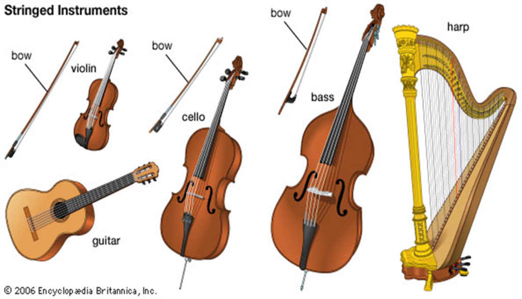
A mechanical amplifier is necessary in the case of a piano or a sounding box in the case of guitar or violin, so as to provide a much louder sound because the strings do not produce a loud sound on their own because they are only able to set a small mass of air into vibration
Percussion instruments
Typical examples include drums, bells, tuning forks, gongs, xylophones, etc.
They produce sound when hit or struck. These sounds however have a short duration. Cords around the rim of a drum enables the player to change the pitch of the note when he sets the elastic membrane into vibration by a strike
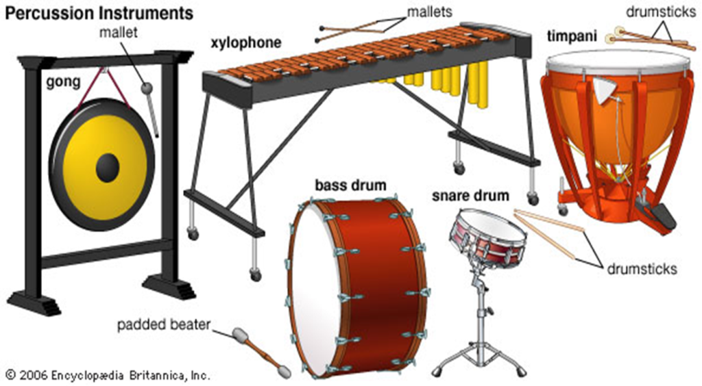
Wind instruments
These instruments produce sound by vibrating air
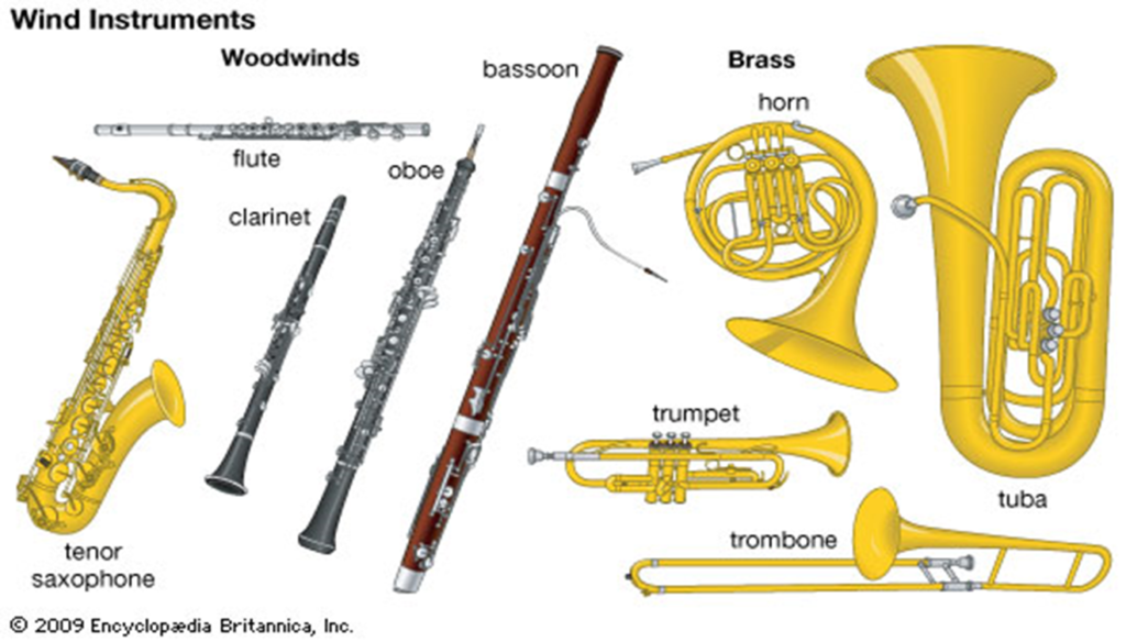
ELECTRICITY
Direct Current Electricity
When an electric charge is in motion, an electric current is produced and it is referred to as current electricity.
When this motion takes place in a closed conducting path, we have an electric circuit.
The electric circuit is the heart of any electric device whether in small applications like mobile phones, televisions, computers, light bulbs or industrial appliances like generators, electric motors, transformers etc.
Electric current
Electric current I is defined as the rate of flow of electric charges Q along a conductor per unit time t.
Current (I)= (quantity of charge (Q))/(time (t))
I=Q/t
The unit of current is Ampere (A)
Quantity of electricity is measured in coulombs and time in seconds
If 6 coulombs (6C) of electricity passes through a conductor wire in 3 seconds, the current is
I=6/3=2A or 2 coulombs per second
The instrument used for measuring electric current is the ammeter.
Current vary in magnitudes. From units in fridges to hundreds in electric motors and other industrial applications. Milliamperes range (10^(-3), 1mA) are the typical values of current in transistor radio while microampere (10^(-6)A, 1μA) are the values of current in mobile phones.
A galvanometer can detect currents thousand of times smaller than 1 microampere (1μA)
To measure current, the ammeter must be connected in a circuit in such a way that the current flows directly through it. That is, in series.
Electric circuit
This is the path through which an electric current flows. In its simplest form a circuit consists of 4 parts:
A source of electrical energy e.g. a battery connected to a
Load e.g. electric bulb and a
Switch through a
Conductor e.g. copper wire
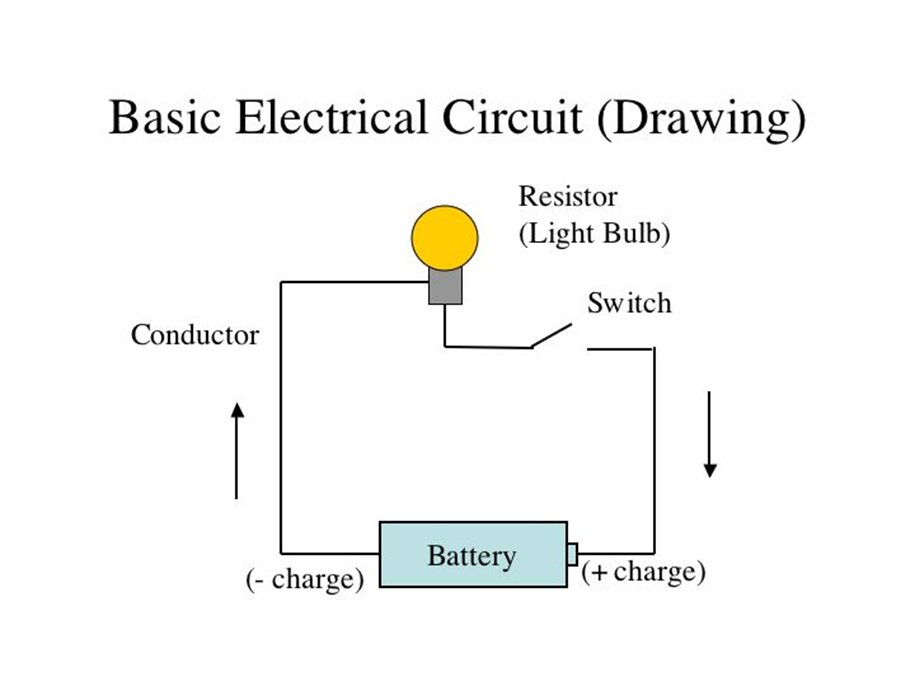
Types of Circuits: Open, closed and short
An electric circuit can be open, closed or short.
An open circuit is a circuit where there is a gap or when the key is open (i.e. the switch is off) in the conducting path. An electric current cannot flow through air.
So if the conductor wire is cut somewhere, the current cannot flow and the circuit is open so the bulb does not light up.

A short circuit in one in which there is no load connected but is closed.
A short circuit causes sparks and may damage the battery

A closed circuit is when the key is closed or the switch is off and no break in flow elsewhere in the circuit.
The current will flow from the battery through the load and the bulb lights up.
The path must be closed (complete) before a current flows.

Potential difference (p.d)
The potential difference between two points is the workdone (in Joules) when 1 coulomb of electric charge moves from one part to another.
Electric current will flow when there is a potential difference between the ends of the wire. Current flows from a point of higher potential to a point of lower potential. This is analogous to water flowing from a higher to a lower level (height difference). The point of higher potential may be said to have a ‘positive’ potential and the lower potential ‘negative’ potential.
The unit of potential difference (p.d) is volts (V). The instrument used for measuring p.d is the voltmeter
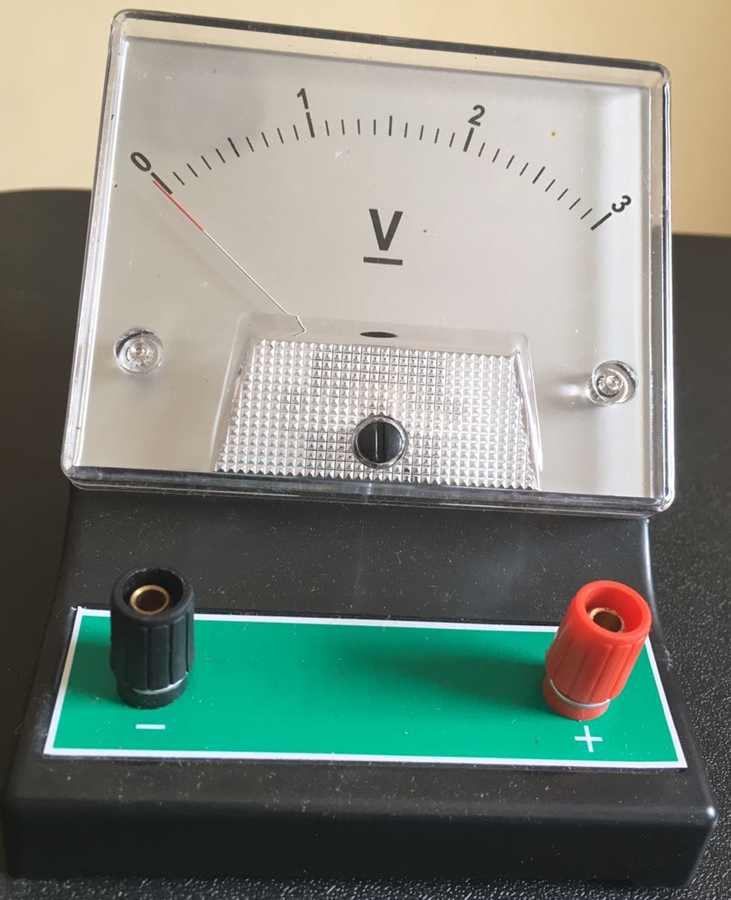
The instument used for measuring current is an ammeter
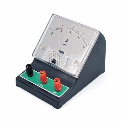
A battery serves as a source of potential difference and is said to have electromotive force (e.m.f) when it is able to maintain a current in a circuit.
Electromotive force is the total workdone in driving an electric charge round a circuit. It is also measured in volts.
We say for example that the emf of a battery is 12 volts while the p.d across lamp 1 is 4V and the p.d across lamp 2 is 8V.

Since potential difference is a measure of the difference in potential between two points, to measure it there, the voltmeter must be connected across (in parallel) with these points.
Circuit symbols
Symbols are used to represent elements or measuring metres.


Resistance
This is the opposition to the flow of electric current.
It is measure in ohms Ω (Greek letter ‘Omega’).
Conductors and insulators
Substances that allow electric current to flow easily through them are called conductors.
Those that do not allow current to flow are called insulators or poor conductors.
Examples of conductors include
metals e.g. silver copper, aluminum
Salt solutions
Inorganic acid solutions
Examples of insulators include air, wood, plastic, glass, pure water, ebonite, organic acid solutions.
Silver is the best metallic conductor known. This is followed by copper.
Pure copper inside plastic materials or flex are used as connecting wires and electric cables in domestic use.
Silver of course cannot be used because it is very expensive.
Since conductors allow the flow of electric current easily, they have low electrical resistance and insulators have high electrical resistance.
Nichrome and magnanin are two alloys of copper with high resistance and they are used as resistance wires
The insulating strength of materials can however break down and they become conductors under certain conditions.
For example, at normal pressure, air is an insulator. But during thunderstorm, we see the conducting path of the lightning flashes in the air.
Charge carriers
The electric current in solids, liquids and gases is carried by tiny particles carrying charges.
A charge may be positive or negative.
| Substance | Charge carrier |
| Metals | Electrons (-) |
| Salts and acid solutions | Ions (+ and -) |
| Gases | Electrons (-) and ions (+) |
| Semi-conductors e.g. silicon | Electrons (-) and holes (+) |
Ohm’s law
It states that the current through a metallic conductor is directly proportional to the potential difference applied across it provided temperature and other physical quantities are kept constant.
Mathematically, I∝V
Where I is the current and V is the potential difference
V/I=constant
The constant of proportionality is the resistance r of the conductor.
When a potential difference V is 1 volt causes a current I of 1A to flow through a conductor, then the resistance of the conductor is 1 ohm (1Ω)
Hence V/I=R and
V=IR
From the equation, it follows that when R is large, I will be small for a constant V
And when R is small, I will be large.
Ohm’s law holds true for metallic conductors and certain alloys but is however not obeyed in some other circuit components such as diodes, transistors, rectifiers, gases, radio valves etc.
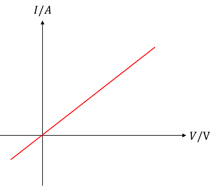
The I-V characteristic for a metallic conductor
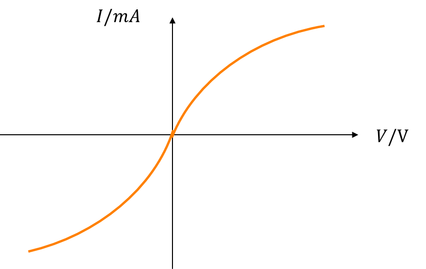
The I-V characteristic for a filament lamp
The graph is not a straight line because the resistance of the lamp depends on the temperature of the filament.
These types of temperature dependent resistors are used in fire sensors, baby-alarms, water temperature sensors in cars
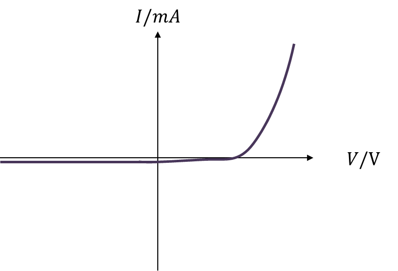
The I-V characteristic for a semi-conductor diode
A diode is any component that allows electric current to flow in only one direction. It is used as rectifiers and in LEDs (light Emitting Diodes).
The resistance of the diode decreases drastically for voltages greater than 0.6V
*
Factors affecting the resistance of a wire
1. Length of conductor: the resistance of a conductor directly proportional to its length i.e. R∝l
2. Cross-sectional area: the resistance of a conductor decreases as cross-sectional area (or thickness) increases R∝1/A
3. Temperature: the resistance of a conductor varies directly with temperature R∝T. For metallic conductors, the higher the temperature, the higher the resistance.
Certain alloys especially constantine and magnanin show very little changes in resistance when temperature changes and are used in making constructing standard resistors
4. Nature of the material: the type of material used in making the conductor also plays an important role in the resistance of the conductor.
The same length, temperature and area of silver, copper or aluminum wire will show different resistance
Combining 1 and 2, we have R∝l/A
Experiments show that at constant temperature, the resistance R of a conductor is related to the length l, cross-sectional area.
According to the equation R=ρl/A
Where ρ (Greek letter ‘rho’) is a constant called the resistivity of the material.
Resistivity depends on the nature of the materials and thus differs from material to material.
If R is measured in ohms (Ω), l in metres m and A in m^2, then ρ has units of Ωm (ohm-metre)
Example: In an experiment to measure the resistivity of a wire material, the following measurement were made:
i) Length =1.0m
ii) Diameter =0.5mm
iii) Resistance =3Ω
Calculate the resistivity
From R=ρl/A, ρ=RA/l
A=πr^2=π(0.5/2)^2, r=(0.5×10^(-3))/2
A=6.25π×10^(-8) m^2
The cross-section of a conductor is a circle
ρ=(6.25π×10^(-8)×3)/1=
Resistivity of some materials
| Conductors (Metals) | Restivity ρ (Ωm×10^(-8) ) |
| Copper | 1.72 |
| Mercury | 95.00 |
| Lead | 22.00 |
| Tungsten | 5.25 |
| Magnanin | 44.00 |
| Constantan | 49.00 |
| Semi Conductors | |
| Pure silicon | 2300 |
| Pure carbon | 35 |
| Pure germanium | 0.60 |
| Insulators | Resitivityρ (Ωm) |
| Glass | 10^10-10^14 |
| Mica | 10^11-10^15 |
| Wood | 10^8-10^11 |
Arrangement of Resistors
Resistors in series

This is the connection of resistors end to end such that the same current flows through them.
The three resistors R1, R2 and R3 are connected in series and the same current flows through the three resistors but the potential difference across each resistor varies.
The total p.d across them V=V1+V2+V3 where V1 is the p.d across R1, V2 across R2 and V3 across R3.
If R is combined resistance, then V=IR and V_1=IR_1, V_2=IR_2, V_3=IR_3
IR=IR_1+IR_2+IR_3
IR=I(R_1+R_2+R_3 )
R=R_1+R_2+R_3
The total resistance of resistors in series is the sum of resistance
Resistors in parallel

When resistors are connected side-to-side such that their ends are joined together and the same p.d is applied across each resistor, then they are said to be in parallel.
Current I_1, I_2 and I_3 flow through resistance R_1, R_2 and R_3 respectively.
The total current from the battery is given as I=I_1+I_2+I_3
If R is the combined resistance,
then V/I=R and I_1=V/R_1 , I_2=V/R_2 and I_3=V/R_3
V/R=V/R_1 +V/R_2 +V/R_3 =V(1/R_1 +1/R_2 +1/R_3 ) 1/R=1/R_1 +1/R_2 +1/R_3
For two resistances in series, the resistances act as a potential divider in the ratio of their resistances.
For two resistances in parallel, the resistances act as a current divider in the ratio opposite their resistances.
*
Example: two resistors of resistance are connected together, find the equivalent resistance when they are connected in a) series b) parallel
a) Let R_1=3Ω and R_2=6Ω
Then equivalent resistance R=R_1+R_2=3+6=9Ω
b) 1/R=1/R_1 +1/R_2 =1/3+1/6=(3×6)/(3+6)=9/18=1/2
R=2Ω
Some tips in series and parallel resistance connections
1. The equivalent resistance of resistance in series is bigger than the biggest, but for resistances in parallel, the equivalent resistance is smaller than the smallest.
2. For 2 resistors in parallel, the equivalent resistance is given as product/sum of resistances
Example: In the circuit diagram, find
i) The equivalent resistance
ii) The current I.

The connection of the resistors is a combination of series and parallel connections.
The 2Ω and 4Ω are in parallel (2||4), the equivalent resistance is given as
1/R=1/2+1/4=3/4
R=4/3 Ω
Alternatively, equivalent resistance = product/sum=
(2×4)/(2+4)=8/6 or 4/3 Ω
If we now replace the 2Ω and 4Ω parallel connection with a single resistance (=4/3 Ω).
This resistance is now in series with the 3Ω (4/3+3)
Equivalent resistance =4/3+3=13/3 Ω
This is the equivalent resistance of the circuit.
To get the current I, we use Ohm’s law (V=IR)
V=12V, R=equivalent resistance=13/3 Ω
I=V/R=12/(13/3)=36/13 A or 2.8A
*
Electrical energy and Power
Electrical energy is dissipated when a quantity of charge moves from one point to another. We earlier defined the potential difference as the workdone W in Joules in moving a quantity of charge Q between two points with potential difference V i.e. W=QV
We obtain a more useful formula when we substitute Q=It. Then W=IVt
From Ohm’s law, V=IR and W=I×IR×t
W=I^2 Rt
This electrical energy can be transformed to many other useful forms of energy as in
i) Heat energy for example in electric iron, electric heaters
ii) Mechanical energy e.g. electric motors, electric fans, washing machines
iii) Sound energy in loudspeakers, telephone ear-piece
iv) Light energy e.g. in filament lamps and electric bulbs
Electric power
We understand generally that power is the rate of doing work, and that power
P=(workdone or energy transferred)/(time taken)
In electricity therefore, power P=IVt/t
P=IV
Where I is the current in Amperes and V is the potential difference in Volts
The unit of power is Watt (W) or Joule per second
Also, P=I^2 R=V^2/R
Example: Find the power in an electric heater carrying a current of 8A when the p.d across it is 120W.
P=IV, I=8A, V=120V
P=8×120=960W
Larger units of power include kilowatts (KW=10^3 W) used in large air-conditioning systems. Megawatts (MW=10^6 W) used in electric power generating stations or industrial generators.
1 horse power = 746W ≅3/4 KW
Electric appliances usually have ratings marked on them in Watts and in volts e.g. a mark of 1000W, 220V on a filament heater means that the appliance supplies a power of 1000W (1000 joules in one second) when connected to a circuit that maintains a p.d of 220V.
Commercial units of electric power and energy
Electric energy consumed in homes and industries is sold in kilowatt-hour.
This is the unit the Power Holding Company of Nigeria (PHCN) measures and sells electrical energy.
1 Kilowatt-hour is the energy consumed when 1 kilowatt of power is used for 1 hour.
1 KWh=1KW×1hr
=1000W×60×60seconds
=3.6×10^6 Joules
Thus if a 60W electric bulb is used for 18 hours, it has consumed 60/1000 KW×18hours
1.08 KWh or 1.08 units
If the charge is N20 per kilowatt-hour, then the electrical cost is 1.08×20=N21.6
Example: Six 100W lamps and four 60W bulbs were used throughout for 2 days. If the electric company charges N20 per kilowatt-hour, calculate the total operating cost during this period.
Lamps: (6×100)/1000 KW×(2×24)hrs=28.8KWh
Cost =28.8×20=N57.6
Bulbs: 4×60/1000×2×24=11.52KWh
Cost: 11.52×20=N23.04
Total operating cost =57.6+23.04=N80.64
FIELDS
Concept of fields
A field is a region of space where the effect of a physical quantity e.g gravitation, heat, electricity etc can be felt.
A force field has been defined as a type of force that need not be in contact with the body before it is applied. There are two classes of fields – scalar fields and vector fields.
A scalar field has only magnitude but no direction e.g. distribution of temperature, density, energy, etc
A scalar field has only magnitude but no direction e.g distribution of temperature, density energy etc.
A scalar field is mapped out by lines such as lines of isothermal, lines of equidensity.
A vector field has both magnitude and direction e.g gravitational field, electric and magnetic field. A vector field is shown by lines of flux or lines of force.
The main focus in this topic is on vector fields.
GRAVITATIONAL FIELDS
It is a common saying that what goes up must come down. If we throw up objects, they move up to their highest points, stay stationary for a moment and then begin to move downwards falling faster and faster until they hit the ground or the lowest level in their path.
This is the influence of gravity on the object.
The pull of gravity acts on masses of all sizes and it permeates all spaces.
Everything around the earth even up the moon is in the earth’s gravitational field.
The earth attracts every object in its gravitational field. This force of attraction causes all objects to accelerate under its influence termed acceleration due to gravity.
This acceleration is represented by g and has a value of about 9.81ms^(-2). This value is the same for all bodies irrespective of the mass. However, it slightly varies from place to place because the earth is not perfectly spherical.
The value of g is minimum at the equator (about 9.78ms^(-2)) and maximum at the poles, the north and south pole (about 9.83ms^(-2))
Thus all bodies in the same locality will fall to the ground in the same time when released from the same height above the ground.
Strictly speaking, a feather and a stone will fall to the ground at the same time if released from the same height.
It is the existence of air that makes the above statement to sound ridiculous.
Newton’s law of gravitation
Isaac Newton, in the year 1666 discovered a universal law of gravitation
It states that the force of attraction F between two masses m_1 and m_2 is directly proportional to the product of their masses and inversely proportional to their distance r apart.
F∝(m_1 m_2)/r^2
F=G (m_1 m_2)/r^2
G is a constant called gravitational constant
If F is in Newtons (N), m_1 and m_2 in kilograms (kg), r in metres (m), then G has unit Nm^2 kg^(-2).
The value of G was found experimentally to be about 6.67×10^(-11) Nm^2 kg^(-2).
Newton’s law of gravitation refers to the force between any two particles or bodies. The force of attraction is actually a pair of forces; an action-reaction pair and has equal magnitude (but opposite in direction) even though their masses may be different.
Gravitational force keeps the moon in its orbit around the earth. Gravitational fore of the sun is also what keeps the earth and other planets revolving around the sun.
Note that gravitational forces are always attractive forces
Gravitational forces between masses
Let us examine the force of attraction on different kind of masses
1. Calculate the force of attraction between the earth with mass of 6×10^24kg and the moon with mass of about 7×10^22kg given that the distance between the earth and the moon is about 4×10^8m F=G (m_1 m_2)/r^2 =(6.67×10^(-11)×6×10^24×7×10^22)/(4×10^8 )^2
2. Calculate the gravitational force of attraction between the electron and proton of a hydrogen atom when the electron moves round the proton, mass of electron = 9.1×10^(-31)kg
Mass of proton =1.67×10^(-27)kg
Distance between electron and proton = 5×10^(-11)m F=G (m_1 m_2)/r^2 =(6.67×10^(-11)×9×10^(-31)×1.67×10^(-27))/(5×10^(-11) )^2
the electrical force of attraction between the proton and the electron is much greater than the gravitational force of attraction.
3. Two spherical balls each of mass 6.0kg are placed so that their centres are 50cm apart. Calculate the gravitational force of attraction between the two balls.
m_1=6.0kg, m_2=6.0kg, r=50cm=0.5m
G=6.67×10^(-11) Nm^2 kg^(-2) F=G (m_1 m_2)/r^2 =(6.67×10^(-11)×6×6)/〖0.5〗^2
Relationship between the gravitational constant G and acceleration due to gravity g.
Let us assume that the earth is a perfect sphere having a radius R and mass M. Let us also assume that this mass is concentrated at the centre of the earth. The distance of an object on the earth’s surface with mass m to the centre of the earth is the radius of the earth.
The gravitational force of attraction between the earth and the object is given by
F=G Mm/R^2
This is also the force of gravity due to the earth on the mass i.e the weight of the body
F=mg
It follows that G Mm/R^2 =mg
g=GM/R^2
This is the mathematical concept employed to obtain the mass of the earth, because of course it is not possible to put a chemical scale under the earth to measure its mass.
gR^2=GM
m=(gR^2)/G
Using value g=9.82ms^(-2), R=6.4×10^6 m, G=6.67×10^(-11) Nm^2 kg^(-2)
m=〖9.81×(6.4×10^6 )〗^2/(6.67×10^(-11) )
=
Example: The earth is four times the size of the moon and 80 times the mass. If the acceleration due to gravity on the surface of the earth is 9.8ms^(-2), what is its value on the moon’s surface.
If the earth is 4×size of moon, then R=4r_m
Where r_m is the radius of the moon and R is the radius of the earth.
Similarly , mass of the earth M=80m_m where m_m is the mass of the moon g_e=GM/R^2 , g_m=(gm_m)/(r_m^2 )
g_m/g_e =(Gm_m)/(r_m^2 )×R^2/GM
g_m/9.8=(Gm_m)/(r^2 m)×R^2/GM
g_m/9.8=m_m/(r_m^2 )×(4r_m )^2/(80m_m )
g_m/9.8=16/80
g_m=9.8×16/80
Gravitational intensity or field strength
The gravitational field strength or gravitational intensity at any point is defined as the force per kilogram mass at that point.
The unit of gravitational field strength or intensity is Nkg^(-1)
If g is the acceleration due to gravity at a point in the earth’s gravitational field, then the force on a mass m placed on that point is F=mg
And force per kilogram mass F/m=g
Gravitational field strength or intensity = g
The field strength decreases above the earth’s surface where it has the value of 9.8Nkg^(-1)
From Newton’s law of gravitation, F∝1/r^2
If G, M are constant and r=R, the radius of the earth, then at a distance 2R from earth’s centre, the field strength g^′=g/2^2 =g/4
*
A satelite, say of mass 1000kg, orbiting the earth at this height 2R will have a gravitational force
=mg^′=mg/4=(1000×9.8)/4=2500N
Whereas on the earth’s surface, it has a gravitational force of mg=1000×9.8=9800N
Gravitational potential
To move a mass from one point on the earth’s surface to a height requires work. The workdone W in raising a mass m from the earth’s surface to a height h above the ground is given by W=mgh
The potential at infinity has the value 0. At a distance r from the centre of the earth, the gravitational potential V is given by V=-GM/r
Where M is the mass of the earth or the mass producing the gravitational field.
G is the gravitational constant
The energy to do this work is termed potential energy or more specifically gravitational potential energy.
We define the gravitational potential V at a point as the workdone in taking 1kg mass from infinity to that point.
Unit of gravitational potential is Jkg^(-1)
Unlike gravitational field strength which is a vector, gravitational potential is a scalar possessing a numerical value but no direction.
Example: Calculate the gravitational potential at a point on the surface of the earth. Take mass of earth = 6×10^24 kg, radius = 6400km and G=6.67×10^(-11) Nm^2 kg^(-2)
V=GM/r, r=6400km=6.4×10^6 m
V=((6.67×1-^(-11)×6×10^24 ))/(6.4×10^6 )
=
The negative sign is not the interest but the magnitude
Gravitational potential C is minus or less than zero because work is done (positive) in taking a mass from that point to infinity. Normally, a body will tend to move on its own from a point of higher gravitational potential to points of lower gravitational potential.
We are sometimes scared of looking down from a tall building or a high platform because a force which is real tends to bring us closer to the centre of the earth but we only get to stop at the surface.
Because g is assumed to be constant close to the earth’s surface, we use the formula mgh to calculate the energy change. If however large changes in position are made corresponding to large distances, we must use the formula V=-Gm/r to calculate the energy change
Escape velocity
For an object to escape from the earth’s gravitational field i.e. go up and not come down, it must acquire a minimum speed, this termed escape velocity.
Suppose a rocket of mass m is fired from the surface of the earth so that it just escapes the earth’s gravitational field. The rocket must possess sufficient kinetic energy to overcome the workdone in taking the mass m from the earth’s surface to infinity.
On the earth’s surface, the potential energy of the rocket equals the product of the mass of rocket and gravitational potential.
m×-GM/R
Where R is the distance from the centre of the earth to the earth’s surface i.e the radius of the earth.
To escape, the kinetic energy 1/2 mv^2 of the rocket is equal to the workdone to take the rocket from the earth’s surface to infinity i.e 1/2 mv^2=0-(-GMm/R)
Or we can say the kinetic energy of the rocket is equal to the gravitational potential difference from the earth’s surface to infinity.
1/2 mv^2=GMm/R
v^2=2GM/R
v=√(2GM/R)
But we know that g=GM/R^2 , hence gR^2=GM and
v=√((2gR^2)/R)
v=√2gR
v is the escape velocity
At the earth’s surface, g=9.8ms^(-2), R=6.4×10^6 m, then
v=√(2×9.8×6.4×10^6 )=11×10^3 ms^(-1) or 11km/s
Thus to escape the earth’s gravitational influence, a rocket must be projected with a minimum velocity of 11km/s.
Satellites
Satellites are placed on rocket to launch them into different orbits in space depending on their mission.
They move around the earth or any other body in space.
Satellites may be natural or artificial (man-made).
The moon is regarded as a natural satellite.
Artificial satellites are human built objects orbiting the earth or other planetary bodies. These satellites are used in
1. communication
2. Weather observation especially in prediction of natural disasters such as earthquakes, volcanic eruptions etc.
3. Scientific research in the study of the earth and other planets and perhaps in the search of extra-terrestrial life.
4. Global positioning system (GPS) used in navigation, location of points and tracking devices.
Some satellites move around the earth at the same rate of rotation of the earth i.e they have a period of rotation of 24 hours. These satellites this appear stationary as they are in the same spot over the earth always. Their orbit of movement is called a parking orbit.
*
Example: Calculate the speed of a satellite in an orbit close to the earth’s surface where the radius of the orbit is assumed to be equal to radius of the earth of 6.4×10^6 m. Also estimate the period of rotation of this satellite.
*
The centripetal force that keeps the satellite in orbit is equal to the gravitational force of the satellite
F=(mv^2)/r=mg
v^2=rg →v=√rg=√(6.4×10^6×9.8)
=8×10^3 ms^(-1)
ELECTRIC FIELDS
Gravitational fields deal with forces on masses while electric fields deal with forces on charges (quantities of electricity).
Apart from the difference mentioned above, charges in electric field may experience an attractive force or a repulsive force unlike gravitational fields where masses only experience attractive forces.
An electric field is a region of space where a charged body experiences an electrical force.
Coulomb’s law
It states that the force F between two point charges q_1 and q_2 is directly proportional to the product of their charges and inversely proportional to the distance r, separating them.
F∝(q_1 q_2)/r^2
F=k (q_1 q_2)/r^2
Where k is the constant of proportionality and is written as 1/(4πε_o ).
ε_o is a constant called the permittivity of free space or vacuum
F=(q_1 q_2)/(4πε_o r^2 )
If F is in Newtons (N), q_1 and q_2 are in coulombs (C), r is in metres (m), then ε_o has units C^2 N^(-1) m^(-2). It has a value of about 8.854×10^(-12)
For easier calculation, 1/(4πε_o ) is approximated to 9×10^9 Nm^2 C^(-2).
Thus F=9×10^9 (q_1 q_2)/r^2
If the charges are situated in water, during electrolysis for instance, the permittivity of free space ε_o changes to the permittivity of water which is about 80ε_o. Hence the force between charges in water becomes 80 times less than the force in free space.
In general, F=(q_1 q_2)/(4πεr^2 ) where ε is the permittivity of the medium
Given that ε=ε_o ε_r with ε_r being the relative permittivity (ε_r=80 for water)
Relative permittivity of some media
| Solid | ε_r |
| Glass | 5 – 10 |
| Amber | 2.8 |
| Wax | 2 – 2.3 |
| Ebonite | 2.8 |
There are two kinds of charges – positive and negative charges.
All charges fall into one of the two and the general rule is that
LIKE CHARGES REPEL, UNLIKE CHARGES ATTRACT
Thus the force between two positive (or two negative) charges is repulsive, but a positive and a negative charge attract each other.
Example: Two positive point charges of 10μC and 8μC respectively are 8cm apart in vacuum. Calculate the force between them.
q_1=10μC=10×10^(-6) C, q_2=8×10^(-6) C, r=8cm=0.08m
F=9×10^9 (q_1 q_2)/r^2 =(9×10^9×10×10^(-6)×8×10^(-6))/(0.08)^2
=
Consider the force of attraction between an electron and a proton in the hydrogen atom each carrying a charge of 1.6×10^(-19)C separated by a distance of 5.3×10^(-11) m.
| Electrostatic attraction | Gravitational attraction |
| F=9×10^9 (q_1 q_2)/r^2 q_1=q_2=1.6×10^(-19), r=5.3×10^(-11) F=(9×10^9×1.6×10^(-19)×1.6×10^(-19))/(5.3×10^(-11) )^2 = | F=G (m_1 m_2)/r^2 Mass of proton = 1.67×10^(-27) kg Mass of electron = 9.1×10^(-31) kg r=5.3×10^(-11) m G=6.67×10^(-11) Nm^2 kg^(-2) F=(6.67×10^(-11)×9.1×10^(-31)×1.67×10^(-27))/(5.3×10^(-11) )^2 = |
The gravitational force can be seen to be negative compared with the electrostatic force. It is the electrostatic force that is therefore responsible for binding forces in
a) electrons to the nuclei to form an atom
b) atoms to atoms to form molecules
c) molecules to molecules to form liquids or solids
However for large bodies, it is the gravitational force that dominates
Example: Three charges +10C, -20C and 15C are distributed as shown. Find the resultant force acting on the 10C charge.
*
Lines of force in an electric field
We are able to map out the lines of force in an electric field. The lines of force represent the direction of motion of a small positive charge placed at a point in an electric field. Arrow head are indicated on the lines to represent the direction of the force.
*
Properties of field lines
1. The field about an isolated positive charge is radially outward while the field about a negative charge is radially inwards
2. Lines of force start on positive charges and end only on negative charges
3. The number of field lines is proportional to the magnitude of the charge
4. Lines of force do not cross each other or intersect
5. In a uniform field, the lines of force are parallel, straight and uniformly spaced
6. The lines are drawn in such a way that the electric field is proportional to the number of lines crossing a unit area perpendicular to it.
7. The closer the lines are together, then the stronger the electric field in that region.
Electric field strength or electric intensity
The electric field strength or intensity E at any point in an electric field is the force per unit positive charge (q) at that point.
E=F/q
The unit of electric field strength is NC^(-1) (Newton per Coulomb)
*
Consider the field around an isolated positive charge q. To find the electric field intensity at P, a distance r from q, we introduce a small charge q_1 at P.
*
The force F on q_1 is F=(q_1 Q)/(4πε_o r^2 )
Electric field intensity E=F/q_1 =Q/(4πε_o r^2 )
The direction of the field strength is outwards, away from Q if Q is positive and inwards, towards Q if Q is negative.
Example: Calculate the electric field intensity in vacuum at a distance 5cm from a charge of 4nC?
(Take 1/(4πε_o )=9×10^9 Nm^2 C^(-2))
E=Q/(4πε_o r^2 )=(9×10^9×4×10^(-9))/〖0.05〗^2
Example: two similar but opposite point charges -q and +q each of magnitude 6×10^(-8) C are separated by a distance of 8.0cm in vacuum as shown below. Calculate the magnitude and direction of the resulting electric field intensity at point P.
(Take 1/(4πε_o )=9×10^9 Nm^2 C^(-2))
The electric field intensity E_1 as a result of the charge -q is towards it (to the left), the magnitude of E_1 is E_1=-q/(4πε_o r^2 )
q_1=6×10^(-8), r=5cm=0.05m
E_1=(9×10^9×6×10^(-8))/〖0.05〗^2 =
E_2=(+q)/(4πε_o r^2 ), q=6×10^8, r=0.03m
E_2=(9×10^9×6×10^(-8))/(0.03)^2 =
The electric field intensity E_2 due to positive charge +q is away from it (also to the left) as a ‘unit positive charge at P is repelled by charge q’
The resultant field intensity E=E_1+E_2=
And is directed towards the charge -q leftwards
Electric potential
In gravitational field, work must be done to move a mass m from a point to infinity. The gravitational potential at a point was defined as the workdone in bringing a unit mass from infinity (where potential is 0) to that point. Similarly, since forces act on charges in an electric field, work is done when charges move from one point to another.
The electric potential V at a point is defined as the workdone per coulomb in moving a positive charge from infinity to that point against the action of the electric field.
The unit of electric potential is JC^(-1) or volts V.
It also has a unit of volts V because in current electricity, the potential difference between two points was defined as the workdone in Joules when a unit positive charge is moved from one point to another
workdone(W)/charge(Q) =electric potential V
W=QV
If work is done AGAINST the field, the potential is positive, if work is done BY the field, the potential is negative
The expression for electric potential V due to a charge Q is give as V=Q/(4πε_o r)
Like gravitational potential, electric potential is a scalar quantity i.e. it has only magnitude without direction
The electric potential at infinity is taken to be zero, but in practical terms, it is the earth that is taken to be at zero potential.
Example: Calculate the potential at a point 15c from a charge of 4μC
V=Q/(4πε_o r)
Q=4μC=4×10^(-6) C, r=15cm=0.15m
V=(9×10^9×4×10^(-6))/0.15=
Example: A small positive charge q of +3×10^(-8) C is placed at O shown.
*
Find the potential
i) At A, distance 10cm from O
ii) At B, distance 20cm from O
What is the potential difference between A and B.
(Take 1/(4πε_o )=9×10^9 Nm^2 C^(-2))
i) Electric potential at A = V_1=q/(4πε_o r)=((3×10^(-8)×9×10^9 ))/0.1
=2700N
ii) Electric potential at B, V_2=(9×10^9×3×10^(-8))/0.2=1350V
Potential difference between A and B = 2700 – 1350 =1350V
Because A is at a higher potential than B, it means that the workdone in moving a charge from B to A (against the field) is 1350JC^(-1).
Relationship between the electric field intensity E and electric potential V
Consider two metal parallel plates A and B, separated by a distance d with a potential difference C applied between them by connecting a battery to the plates. The electric field between the plates is uniform as shown by the parallel lines of force. The field strength E is then constant in magnitude and direction.
Suppose a positive charge q is moved from a point X on plate B to Y on plate A opposite the direction of the intensity E, then the workdone by the charge is given by
Workdone = force × distance = qE×d
Also workdone = QV
QE×d=QV
E=V/d
The ratio V/d is called the potential gradient of the field between the plates. The unit of potential gradient is ‘volt per metre’ or V/m. It measures the change in potential with distance in an electric field. The greater the potential gradient, the greater will be the electric field strength.
Example: Two parallel plates are charged to a p.d of 200V. If they are separated by a distance of 10cm, calculate the electric field intensity between them.
E=V/d=200/10=20Vm^(-1)
Capacitors and capacitance
A capacitor is a device for storing electric charges or electricity. It consists essentially of two metal plates (conductors) separated by an insulator. The plates usually carry an equal and opposite charge such that the net charge on the capacitor is zero.
Capacitors are widely used in all electronic appliances such as television set, radio and many others.
The insulator is called a dielectric substance
Charging and discharging a capacitor
*
When a capacitor is connected to a battery, the positive pole of the battery attracts electrons (negative) from plate A and they are pushed round the circuit so electrons flow from the negative pole of the battery to the plate B of the capacitor. Thus the plate B has negative charge and A an equal amount of positive charge. The capacitor is now said to be charged. The electron flow ceases (or current stops) when the electrons at B repel other electrons and so they are unable to reach B. The process of charging is completed in a very short time
Discharging a capacitor
If the plates of a charged capacitor are joined by connecting a wire between capacitor plates A and B, a spark may be seen as the plates are joined.
*
Electrons now flow from plate B to A (the negative plate to the positive plate) until the positive charge on A is completely neutralized. A current thus flows for a short time interval after which the capacitor is said to have been discharged.
Capacitance
It is the ability of a capacitor to store electric charges defined as the ratio of the charge Q on either plates to the potential difference V between them.
capacitane C=charge(Q)/(potential difference (V) )
The unit of capacitance is the Farad (F)
1F is the capacitance of the capacitor when 1 V potential difference provides a charge of 1C.
Practically, 1F is the capacitance of a large capacitor. Capacitors in circuits of radio, TV and other electronic equipment have their capacitance in microfarads (μF).
1μF=10^(-6) F Smaller units are nanofarads nF(10^(-9) F) and picofarads pF(10^(-12) F)
Factors affecting capacitance
The capacitance of a capacitor depends on the
1. area (A) of the plates
2. distance (d) separating the plates
3. nature of the insulating material (dielectric substance) used i.e. the value of ε
Paper, air, glass, mica, and other insulators have varying dielectric constant or permittivity
Experimentally, these factors are related to the capacitance C of a capacitor according to the formula C=εA/d
C=(ε_o ε_r A)/d
Where ε=ε_o ε_r
ε_r is the relative permittivity of the insulating medium
ε_o is the permittivity of free space
Example: A parallel-plate capacitor with a cross-section area of 12cm^2 is used to store electric charges when a p.d of 60V is applied. If the distance between the plates is 3cm and the insulating medium is a vacuum, calculate the
(i) capacitance of the capacitor
(ii) charge on each plate
(iii) capacitance of the capacitor is the medium is mica with relative permittivity of 5
(Take ε_o=8.85×10^(-12) C^2 N^(-1) m^(-2))
C=εA/d
A=12cm^2=12×10^(-4) m^2, d=3cm=0.03m
For vacuum, ε_r=1 and ε=ε_o ε_r=ε_0
(i) ∴C=((8.85×10^(-12)×12×10^(-4) ))/0.03
=
(ii) C=Q/V, then Q=CV=
For mica, ε=ε_o ε_r=5ε_o
C=(5ε_o A)/d=
Arrangement of capacitors
As in resistors, capacitors may be arranged in series or parallel.
Series arrangement of capacitors: when two or more capacitors are connected end-to-end.
*
The charge Q stored by each capacitor is the same
The potential difference across C_1 is V_1, across C_2 is V_2 and across C_3 is V_3
V=V_1+V_2+V_3
Q/C=Q/C_1 +Q/C_2 +Q/C_3
Equivalent capacitance 1/C=1/C_1 +1/C_2 +1/C_3
Parallel arrangement of capacitors
Now consider three capacitors connected in parallel
The potential difference V across each capacitor is the same. Let the charge on C_1 be Q_1, on C_2 be Q_2 and on C_3 be Q_3
Then total charge Q=Q_1+Q_2+Q_3
CV=C_1 V+C_2 V+C_3 V
“Equivalent capacitance ” C=C_1+C_2+C_3
Note the difference in finding the equivalent capacitance and equivalent resistance in series and parallel arrangement
| Resistor | Capacitor |
| Series: Different voltage, same current R=R_1+R_2+R_3 | Different voltage, same charge 1/C=1/C_1 +1/C_2 +1/C_3 |
| Parallel: 1/R=1/R_1 +1/R_2 +1/R_3 Different current, same voltage | C=C_1+C_2+C_3 Different charge, same voltage |
Example: Two capacitors of capacitance 6μF and 8μF are connected in series and the resulting combination is connected to a potential difference of 140V. Calculate
i) the equivalent capacitance
ii) the charge on the 8μF capacitor
A circuit diagram is shown
*
i) The equivalent capacitance C is given by 1/C=1/6+1/8
1/C=7/24
∴C=24/7 μF
ii) Charge Q on the combination Q/C=Q/C_1 +Q/C_2
Q=CV=24/7×140=480μC
Since the charges are equal in series combination, charge on 8μF capacitor =480μC
Energy stored in a charged capacitor
Capacitors store electric charges so they can be a source of electrical energy. While charging a capacitor, the potential difference builds up from an initial value of 0 to a final value of V. The capacitor then acquires a charge Q.
The average value of the p.d across the capacitor then becomes (0+V)/2=1/2 V
And workdone is given by W=1/2 V×Q=1/2 QV Q=CV, ∴W=1/2 CV^2
Also V=Q/C, W=1/2 Q^2/C
Energy stored in the capacitor is thus equal to workdone W=1/2 QV=1/2 CV^2=1/2 Q^2/C
Example: What is the energy stored when a potential difference of 24V is applied across a capacitor of capacitance 5μF?
C=5μF=5×10^(-6) F, V=24V
Energy stored W=1/2 CV^2
W=1/2×5×10^(-6)×24×24
W=1.44×10^(-3) J
Application of capacitors
Capacitors are used
i) for tuning in radio circuits
ii) in the ignition system of cars and other motor vehicles
iii) Smoothening rectified current from d.c power supplies
iv) In impedance matching and power factor correction
v) Reducing noise in a.c amplifiers
vi) Storing large quantities of charge
AC CIRCUITS
Lorem ipsum dolor sit amet, consectetur adipiscing elit. Ut elit tellus, luctus nec ullamcorper mattis, pulvinar dapibus leo.
ATOMIC PHYSICS
Lorem ipsum dolor sit amet, consectetur adipiscing elit. Ut elit tellus, luctus nec ullamcorper mattis, pulvinar dapibus leo.
NUCLEAR PHYSICS
Lorem ipsum dolor sit amet, consectetur adipiscing elit. Ut elit tellus, luctus nec ullamcorper mattis, pulvinar dapibus leo.